BASIC ANALYZER OPERATION
Chapter 4
............
Sievers TOC-R3 Operation and Maintenance Manual
DLM 95000-01 EN Rev. A 141 © Veolia 2023
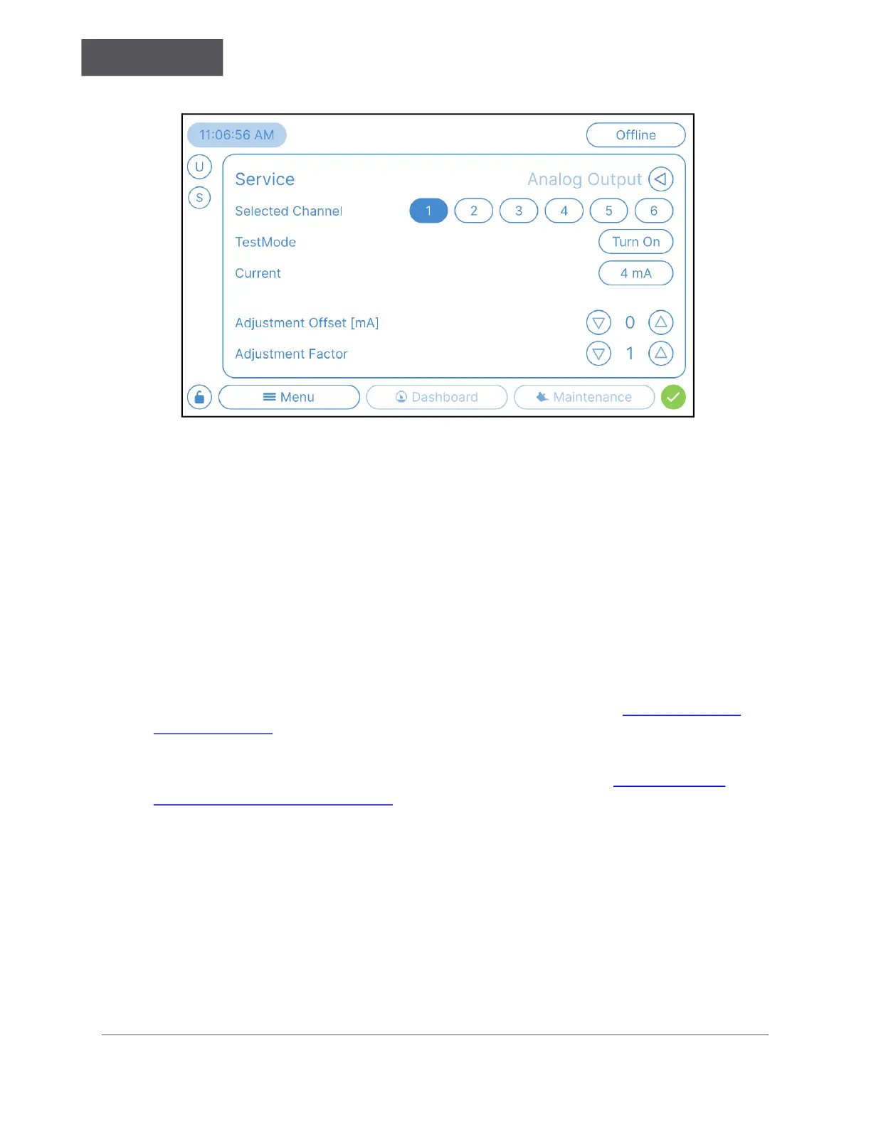
Figure 4-36: Menu → Service → Analog Output → Test
5. The Analog Output Test screen has the following settings:
• Selected Channel
• TestMode — “Turn On” or “Turn Off” the selected output.
• Current — choose the desired output current.
• Adjustment Offset [mA] — only adjusts the selected mA (4, 12.5 or 20 mA)
• Adjustment Factor — adjusts all three points (4, 12.5 & 20 mA) the same amount
Digital Input
Use this screen to set up any wired Digital Input(s). These are only available with the
Optional Communication Box Accessory. For more information, see “Communication
Box” on page 54. Use this instruction for configuring any wired Digital Inputs or to update
the input signal, as needed.
For information about how to test the Digital Input connection, see “Test the Digital
Input(s) (Binary Input)” on page 95.
The four Digital Inputs (Binary) are set by the Analyzer. Each Digital Input channel has a
specific function based on the Analyzer configuration:
• Monitor — Sample Stream Flow Monitoring
• Check — Running a Check Standard Remotely
• Interruption Free — Temporarily Disabling Certain Automated Features

 Loading...