INSTALLATION
Chapter 3
............
Sievers TOC-R3 Operation and Maintenance Manual
DLM 95000-01 EN Rev. A 85 © Veolia 2023
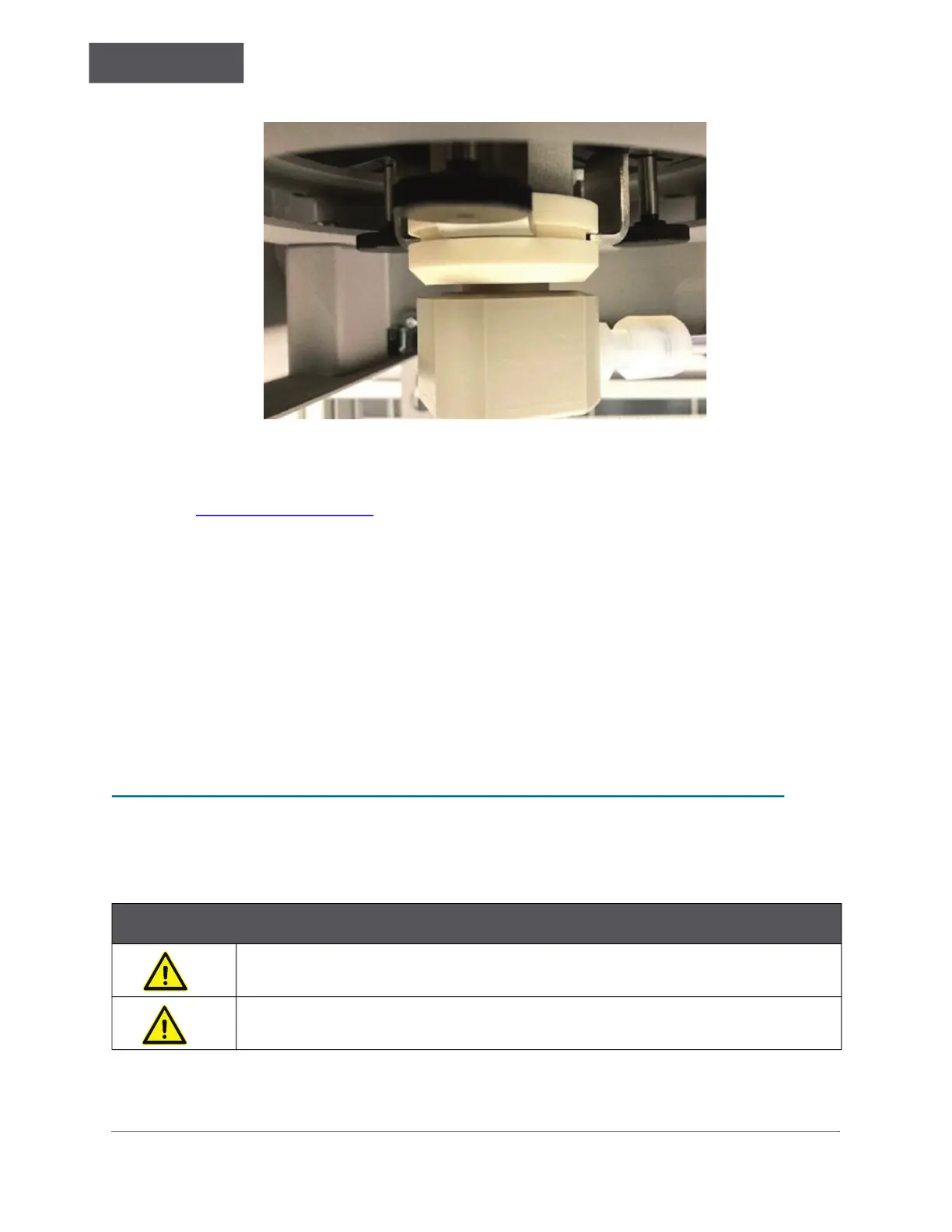
Figure 3-18: Furnace Foot Assembly Z-Brackets in Groove
6. Rotate the Furnace Foot Z-Brackets [13] to slot and clamp onto the Furnace Foot
Assembly [12] groove. Tighten the three Thumb Screws [17] to be finger-tight. See
Figure 3-18 on page 85
. NOTE: This can be difficult due to small access area.
7. Working from the right side compartment into the left side compartment inside the
Analyzer, pull the Transfer Tube through the lower opening toward the Furnace Foot
Assembly [12].
8. Reconnect the Transfer Tube to the Furnace Foot Assembly [12].
9. Set the loose end of the Transfer Tube next to the Gas Cooler Unit in the right side
compartment of the Analyzer. It will be connected in a later step. Do not connect it to
the Analyzer. Leave it open to atmosphere. Failure to do this may result in
hardware failure in the future due to contaminants entering the system.
10. Reinstall the Furnace Access Cover.
STEP 10: CONNECTING TO A POWER SUPPLY
Warning
A qualified electrician must perform all electrical installation activities.
Disconnect all power to the Analyzer when working with electrical connections.

 Loading...