MAINTENANCE
Chapter 6
............
Sievers TOC-R3 Operation and Maintenance Manual
DLM 95000-01 EN Rev. A 213 © Veolia 2023
contaminants. Ensure the section of tubing is longer than the Transfer Tube so it
does not get stuck.
NOTE: The Transfer Tube may be slightly discolored from normal use. This is
expected.
7. Put the Furnace Foot Assembly back together. Insert the small Ceramic Disk into the
center of the Furnace Foot Assembly. Ensure the Disk is laying flat inside the Furnace
Foot Assembly. Important! Failure to install this correctly will result in hardware
failure!
8. Reinstall the Furnace Foot Assembly on to the Furnace Sleeve extending below the
Furnace.
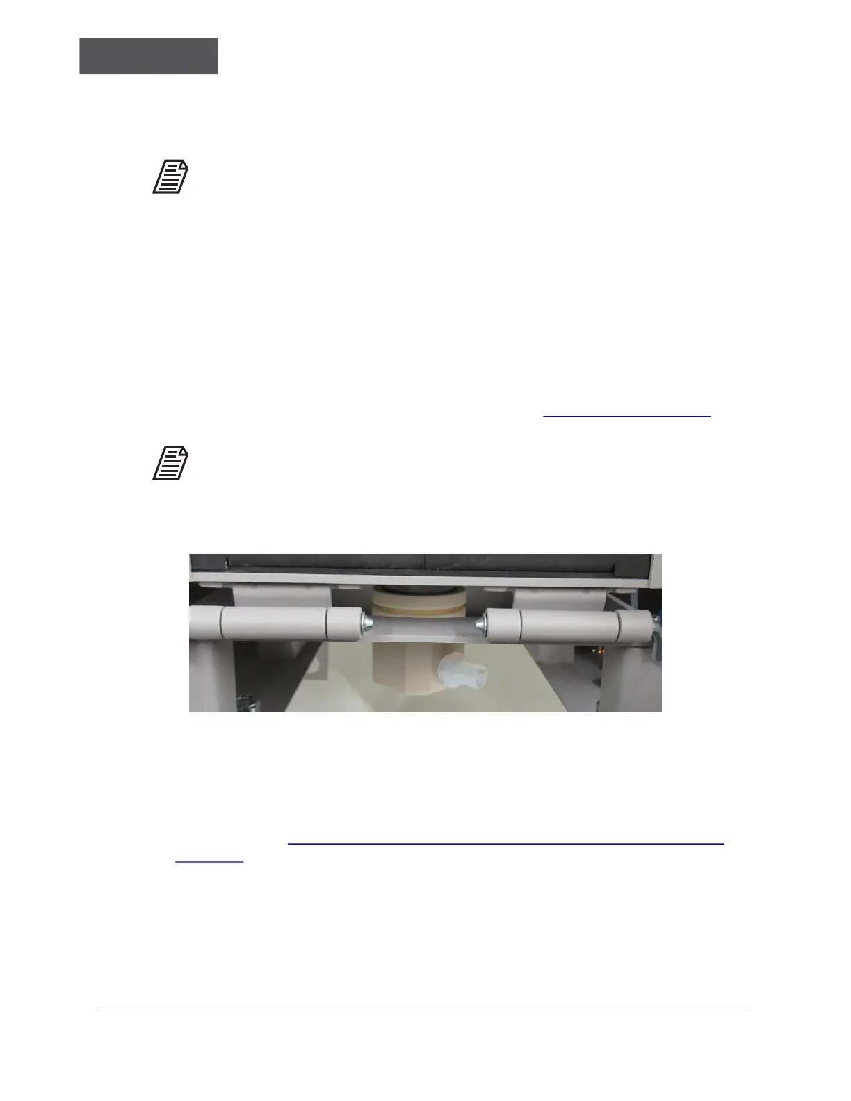
• Working from below through the Furnace Access Port, gently push the Furnace
Foot Assembly on to the bottom of the Furnace Sleeve extending out from below
the Furnace. Ensure the Transfer Tube Port is oriented at a 45° angle between the
Gas Cooler Unit and the front of the Analyzer. See Figure 6-15 on page 213
.
NOTE: If the desired angle is not achieved on first attempt, rotate the Furnace
Foot Assembly [12] anticlockwise until the desired position is obtained. Do
not rotate clockwise or it will loosen the fittings inside the Furnace Foot
Assembly [12] and risk hardware failure!
Figure 6-15: Furnace Foot Assembly correct orientation
9. Reconnect the Transfer Tube to the Furnace Foot Assembly and the Gas Cooler Unit.
Ensure both connections are tight.
10. Navigate to the Menu → Service → Sensors screen. Check the “Carrier Gas Flow
In” and the “Carrier Gas Flow Out” Sensor readings for adequate flow. For more
information, see “Important Sensor Values — Analyzer On, Analysis Stopped” on
page 196.
11. Reinstall the Furnace Access Cover.
12. If planning to perform more maintenance, follow the procedures listed in the
appropriate sections of this chapter. Otherwise, you may turn the Furnace Power
back “On” and close the Analyzer door. The Analyzer will require at least two hours to
reach operating temperature.

 Loading...