BASIC ANALYZER OPERATION
Chapter 4
............
Sievers TOC-R3 Operation and Maintenance Manual
DLM 95000-01 EN Rev. A 145 © Veolia 2023
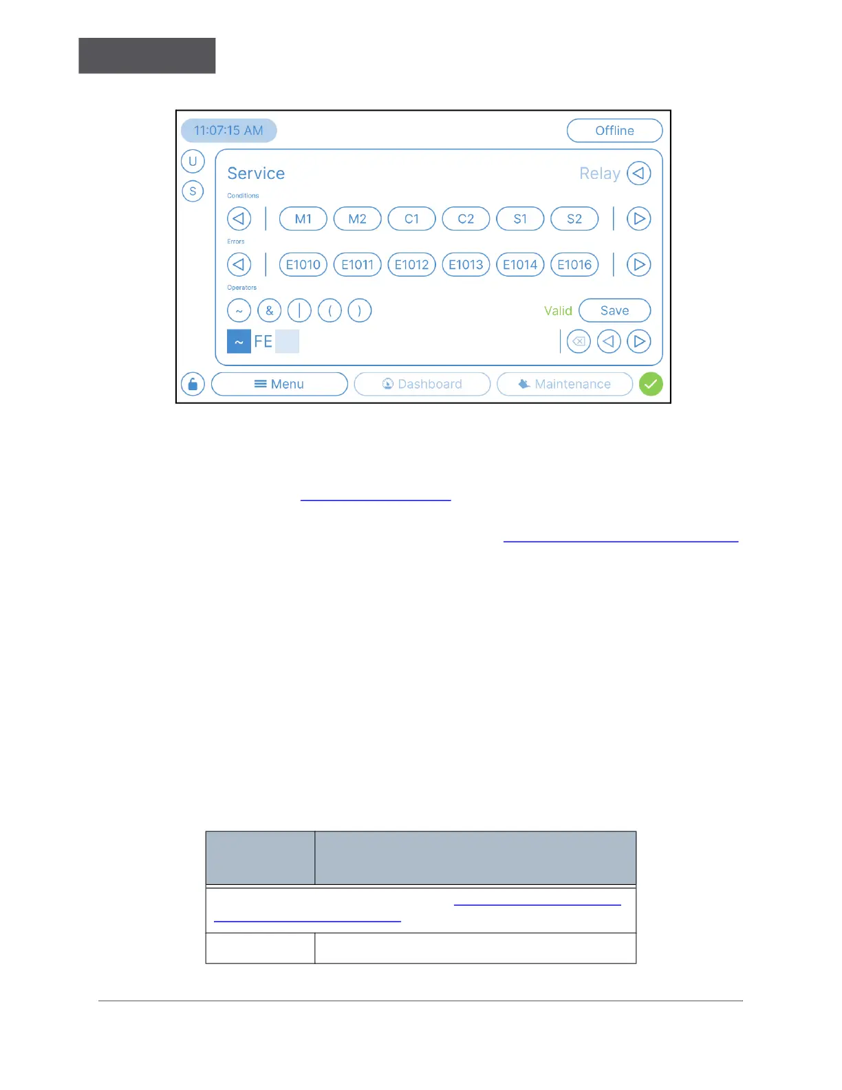
Figure 4-39: Menu → Service → Relay → Relay Definition Screen
5. The Relay Configuration screen displays the following:
• Conditions — Use the Conditions area to define the Conditions for the Relay
Definition. See Table 4-6 on page 145
for a quick reference guide.
• Errors — Use the Errors area to select any Errors for the Relay Definition. For
more information about each Error Code, see “Errors and Warnings” on page 250
.
• Operators — Use the Operators area to define the desired Logic configuration of
the Relay Definition. Use the following symbols to create the Relay Definition.
► NOT (~)
► AND (&)
► OR (|)
► Brackets ( ( ) )
• The bottom of the Relay Configuration screen will display the current “Relay
Definition” as you build it. If needed, use the D
ELETE button and LEFT and RIGHT
arrows to navigate and edit the displayed definition.
• The Relay Definition screen will also provide feedback about the current Relay
Definition and indicate whether it is Valid or not.
Table 4-6: Digital Relay Condition Codes and Descriptions, Short List
Condition
Code
Explanation
For the full list of Condition Codes, see “Analyzer Condition Codes
and Descriptions” on page 258.
M1 Stream 1 Online measurement active.

 Loading...