COMMUNICATION BOX WIRE CONNECTION
. . . .. . . ... .... .... .... ..... ..
Sievers TOC-R3 Operation and Maintenance Manual
DLM 95000-01 EN Rev. A 76 © Veolia 2023
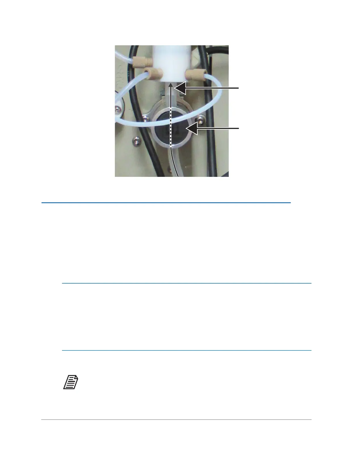
Figure 3-8: Install the MFSV Drain Tubing in the Y9 Pinch Valve
STEP 6: CONNECT THE SAMPLE LINE(S)
The Analyzer has up to two Sample Inlets for analysis. The Sample Inlet Tubing (4 mm OD, 2
mm ID) for each Sample Inlet (Port 7 and Port 6) comes pre-installed from the factory.
Determine the Sampling method you will be using and install the Sample Line(s) to the Sample
Point(s). The flow from the sample source should be disabled until the Analyzer is ready to begin
analysis. Sample flow should remain OFF at this time!
Connecting the Analyzer to a Sample Point
If connecting the Analyzer directly to a Sample Point, ensure the flow has a minimum of
100 mL/min, the sample pressure is within 0-20 kPa (0-0.2 Bar, 0-2.9 psig) and the
Sample Point is within 2 m (6.5 ft) of the Analyzer. This distance cannot be extended.
Connect the Sample Inlet Tubing to the Sample Point connection.
Installing the Particulate Sampler, Optional
NOTE: This accessory uses Metric Standard connections. The Inlet and
Outlet are Slip/Slip (Female) Fittings for DIN 32 Schedule 40 PVC.

 Loading...