COMMUNICATION BOX WIRE CONNECTION
. . . .. . . ... .... .... .... ..... ..
Sievers TOC-R3 Operation and Maintenance Manual
DLM 95000-01 EN Rev. A 86 © Veolia 2023
Connect power to the Analyzer in accordance with local regulations and facility guidelines. A
qualified electrician must perform all electrical installation activities. Ensure all power
connections are made with the POWER OFF.
The Analyzer uses a Universal Power Supply and can operate on both 50 and 60 Hz of AC
power. There are no hardware or firmware setting changes required for using either power
setting.
• 120V @ 60 Hz
• 220V @ 50 Hz
A qualified electrician should make the electrical connections according to your local Electrical
Code, including installing an external switch or circuit breaker required to facilitate maintenance
and servicing of the Analyzer. It should be installed near the Analyzer and be clearly marked as
the disconnecting device for the Analyzer. Ensure all power connections are made with the
POWER OFF.
If using nitrogen zero air or compressed air as Carrier Gas, turn that supply on before powering
On the Analyzer.
If using either the Communication Box and/or Air Box Assemblies, ensure those power
connections are already made. For more information, see Step 3 on page 66
.
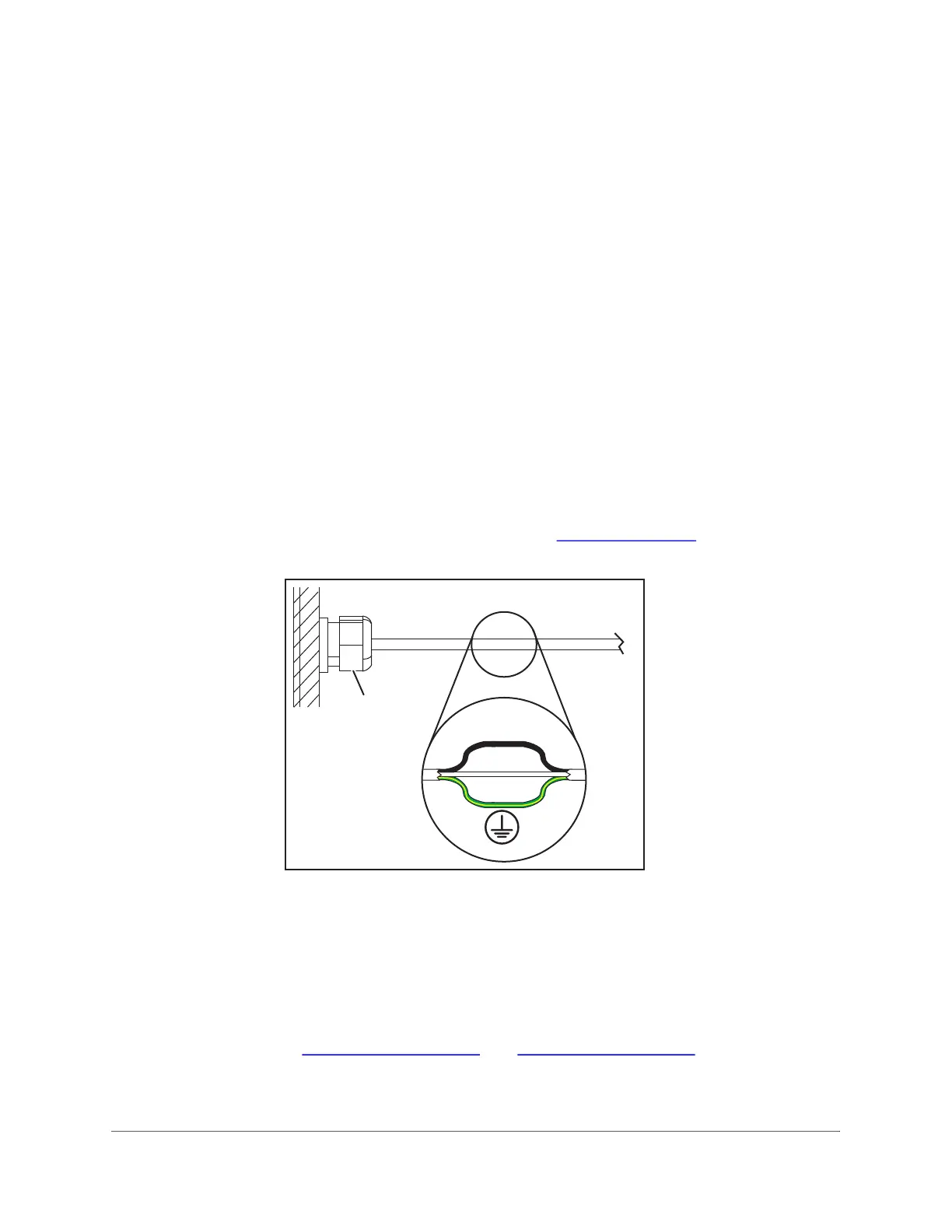
Figure 3-19: Wire Types
• Power ON the Analyzer by turning the Rotary Power Switch on the right side of the
Analyzer to the vertical, ON position.
• Confirm the Analyzer and any installed Optional hardware have power before continuing.
With the Analyzer door open, observe the Gas Cooler Unit in the lower right side
compartment of the Analyzer. The right, Red LED will illuminate while it is cooling down to
temperature. The left, Green LED will illuminate once the system is at temperature (about
10 minutes). See Figure 3-10 on page 79
and Figure 3-20 on page 88.
• Due to the system not being fully connected inside the Analyzer, an Error will appear on
the Touchscreen. This is normal and expected. All Errors will be cleared in a later step.

 Loading...