COMMUNICATION BOX WIRE CONNECTION
. . . .. . . ... .... .... .... ..... ..
Sievers TOC-R3 Operation and Maintenance Manual
DLM 95000-01 EN Rev. A 74 © Veolia 2023
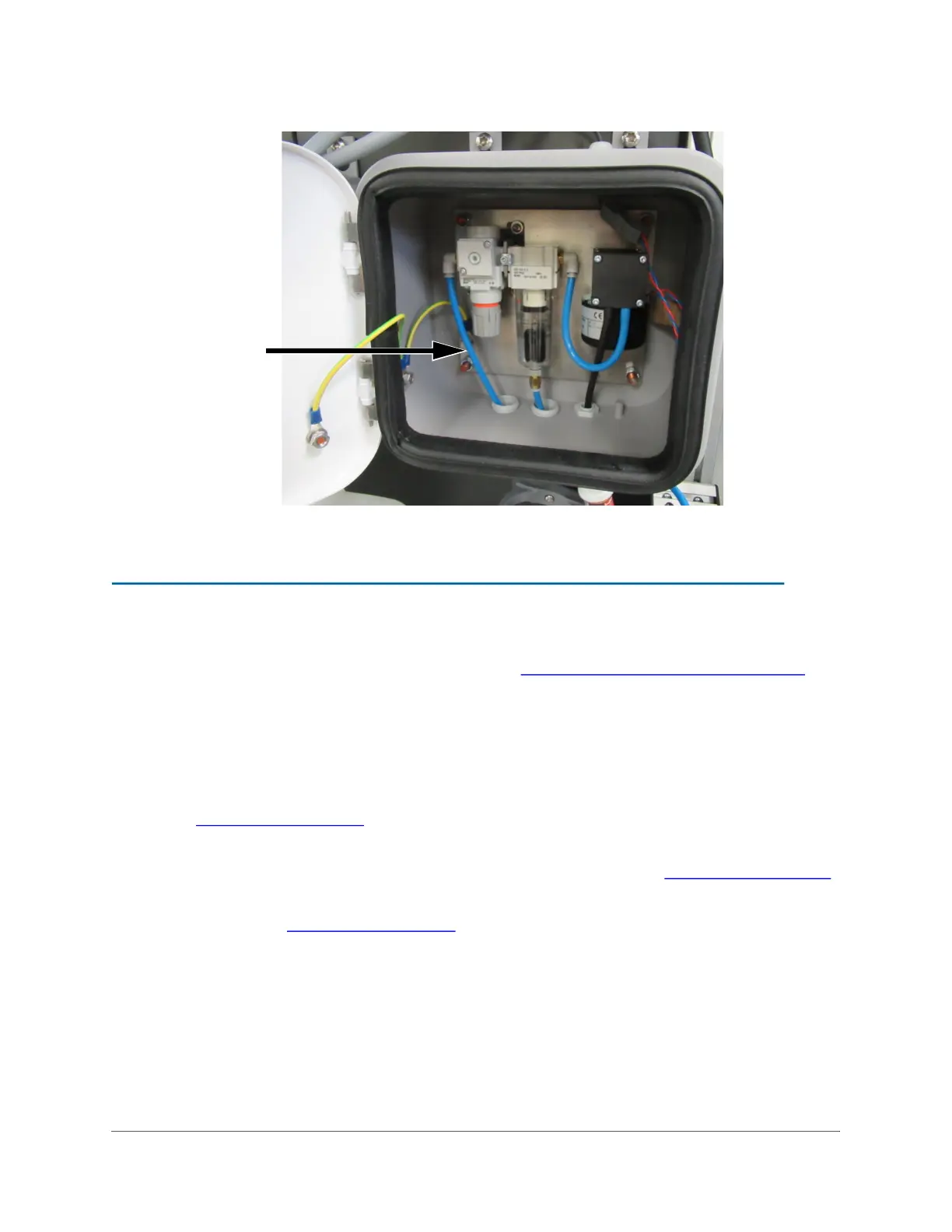
Figure 3-6: Air Box Outlet Tube
STEP 5: CONNECT THE WASTE LINE
Locate the Waste Tubing [18] in the Shipping Kit. See Table 3-1, “Shipping List,” on page 61.
Important! The Analyzer requires a gravity drain with little to no back pressure [less than 7
kPa (0.07 Bar, 1 psig)].
1. Open the Analyzer door and locate the Gravity Drain T-Fitting in the bottom right
compartment of the Analyzer.
2. Route the Waste Tubing up into the Analyzer through Port 2. This can be difficult.
Figure 3-7 on page 75
.
3. Connect the Waste Tubing [18] to the barb on the bottom of the Gravity Drain T-
Fitting. Ensure that the tubing is fully inserted on the barb. See Figure 3-7 on page 75
.
4. Check and confirm that all connections are made and secure on the Gravity Drain T-
Fitting. See Figure 3-7 on page 75
.
5. Route the other end of the Waste Tubing [18] into a free-flowing, ventilated gravity
drain below the Analyzer. Ensure the tubing is and will not be submerged.

 Loading...