DIGITAL INPUT
. . . .. . . ... .... .... .... ..... ..
Sievers TOC-R3 Operation and Maintenance Manual
DLM 95000-01 EN Rev. A 142 © Veolia 2023
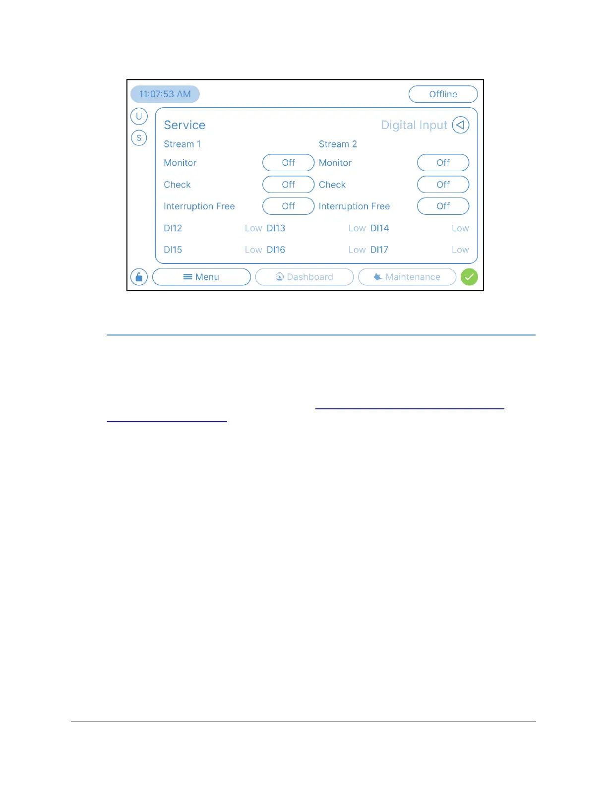
Figure 4-37: Menu → Service → Digital Input
To set up the Digital Input(s)
The Communication Box has four customizable Digital Inputs (Isolated Binary Inputs),
configurable for communicating remote commands to the Analyzer. Use this instruction to
configure any Digital Inputs wired earlier in “Install any Optional I/O or Carrier Gas
Accessories” on page 66.
1. If the Analyzer is taking measurements, press the O
NLINE button in the top right
corner to stop analysis and set the Analyzer to “Offline” Mode. The Analyzer must be
in Offline Mode before Data Management operations are allowed.
2. Navigate to the following: Menu → Service → Digital Input
3. The Digital Input screen displays the current settings for any Digital Input signals.
4. If desired, enable any wired Digital Inputs.
Important! Digital Inputs (Binary Inputs) functions are set by the Analyzer. Each
Digital Input channel has a specific function based on the Analyzer configuration.
► Monitor — When the ‘Monitor’ Digital Input function is activated, the
system will run the Online measurement cycle continuously for the
designated sample line(s) when receiving a constant 24V signal at the
input. Use this setting for samples with intermittent flow. This feature is
used to monitor sample stream flow with a 24V signal from a User-
provided flowmeter or PLC. If the stream has flow (receiving 24V) the
Analyzer will run. If not (24V input stops), the Analyzer either stops and
waits for flow to resume or will continuing running the other stream, if Two-
Stream equipped, enabled, and flowing. If the User wants to measure both

 Loading...