SYSTEM DESCRIPTION
Chapter 2
............
Sievers TOC-R3 Operation and Maintenance Manual
DLM 95000-01 EN Rev. A 41 © Veolia 2023
particular interest for the inlet and outlet of wastewater treatment plants. This Method is a
purchasable option.
SAMPLE FLOW PATH
The Sievers TOC-R3 is available in two primary configurations: Single-Stream or Two-Stream
configurations. The optional Two-Stream configuration has up to two Sample Inlets. For more
information, see Figure 2-2 on page 41
.
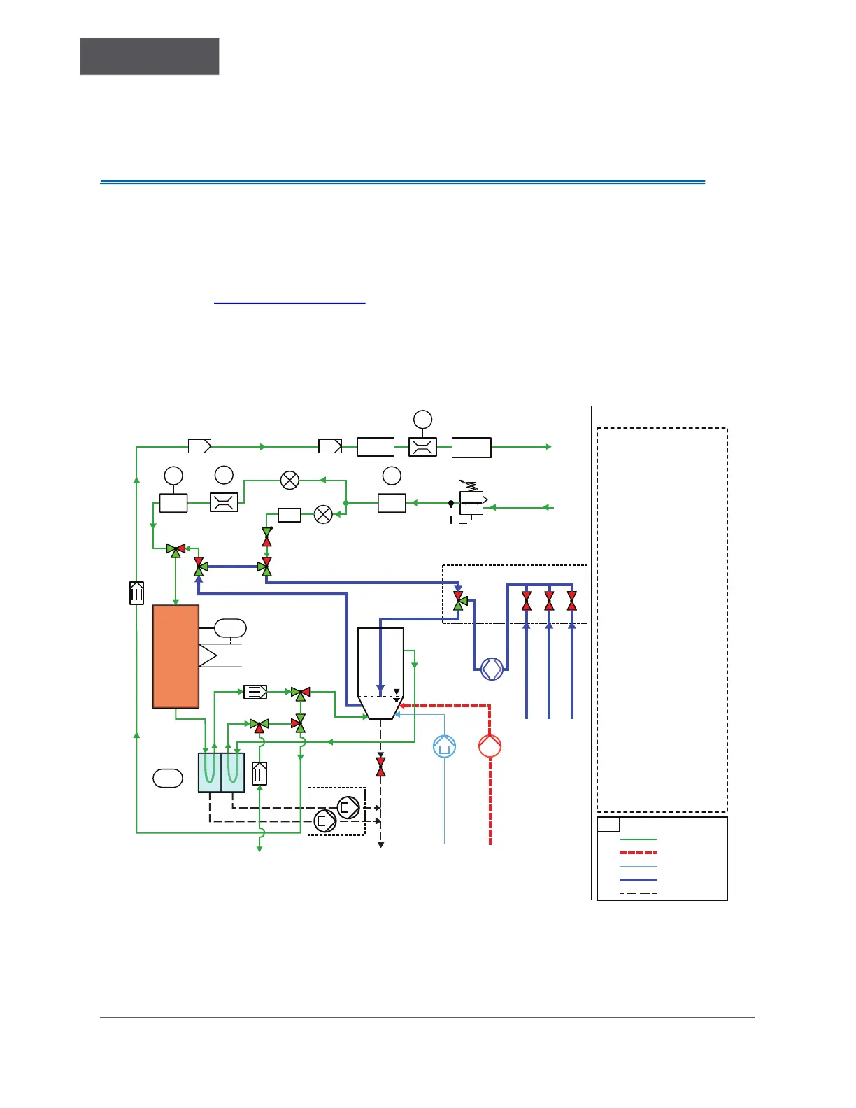
Flow Diagram
Figure 2-2: Flow Diagram
• Green lines represent the Carrier Gas flow path.
• Red line represents the Acid supply.
• Thin, light Blue Line represents the DI Water supply (for Dilution option).
Carrier Gas In
Carrier Gas Out
Calibration/Grab Sample
Sample Stream 2
Sample Stream 1
Gravity Drain
B1 - NDIR Detector
B2 - ECD or PID Detector
BP1 - Reactor Pressure Sensor
BP2 - Nozzle Pressure Sensor
BF1 - Gas Flow Sensor - In
BF2 - Gas Flow Sensor - Out
CM1 - Injection Accumulator
CM2 - Multi-Function Sample
Vessel (MFSV)
EC1 - Gas Cooler Unit
EB1 - Furnace
GP1 - Sample Pump
GP2 - Condensate Pump
GP3 - Acid Pump
GP4 - Dilution Pump
HS1 - Aerosol Absorber
HS2 - Halogen Trap
HS3 - 0.2 μm NDIR Disk Filter
HS4 - 0.1 μm Filter
KH1 - Pressure Regulator
RM1 - Check Valve
RN1 - Carrier Gas Nozzle
RN2 - Injection Gas Nozzle
Y1 - Stream 1 Valve
Y2 - Stream 2 Valve
Y3 - Calibration/Grab Valve
Y4 - MFSV Valve
Y5/6 - Injection Loop Valve
Y7 - Injection Valve
Y9 - MFSV Drain Valve
Y10 - Strip Valve
Y11 - Strip Valve
Y12 - MFSV Vent Valve
RN2
RN1
TOC-R3
I/O
DI Water
MFSV
Vent
Ambient Air
CM1
TICA
el.
EB1
EC1
KH1
BF2
RM1
Y3
Y4
Injection
Loop
Y5
TCA
Y2 1Y
HS3 HS4
HS2
HS1
B1
NDIR
GP2
GP1
BP2
BP1
FA
F
PA
P
PA
P
Y7
Y6
Y10
Y9
Y11
GP4
CM2
Acid
Acid
DI Water
Sample
Waste
*Arrows indicate direction of flow.
GP3
Y12
FA
F
BF1
B2
ECD/PID
Key
Carrier Gas
NC
NC
NO
NO
NC
NO
NC
NC NC NC
NO
NC
NC
NC
NC
NO
NO
NO
I/O
I/O
I/O
I/O
I/O
I/O
Sample Manifold

 Loading...