SYSTEM DESCRIPTION
Chapter 2
............
Sievers TOC-R3 Operation and Maintenance Manual
DLM 95000-01 EN Rev. A 49 © Veolia 2023
Wetted Materials
Use this table to learn about the Wetted Materials within the Analyzer. This list represents
the components that sample interacts with within the Analyzer.
Y5 / Y6 Injection Loop Valves These valves control the sample
injection.
Y7 Carrier Gas Valve This valve controls the Carrier
Gas Flow in to the Furnace.
Y9 MFSV Drain Valve This pinch valve can manually
drain the contents of the MFSV
out to waste. To manually drain
the MFSV, push in the pinch
valve plunger.
a
Y10 / Y11 / Y12 Gas Distribution Module:
Y10: Strip Valve
Y11: Strip Valve
Y12: MFSV Vent Valve
Together, these valves create
the Gas Distribution Module.
This module directs Carrier Gas
through different flow paths
within the Analyzer depending
on the Analytical Method
selected. The Analyzer will open
or close these valves to send
Carrier Gas to the MFSV (used
for sparging), to the NDIR, or out
to waste.
Y12: This valve connects directly
to the MFSV Vent. The MFSV
Vent is open to ambient air.
a. This will drain the MFSV as long as Y12 is open to atmosphere.
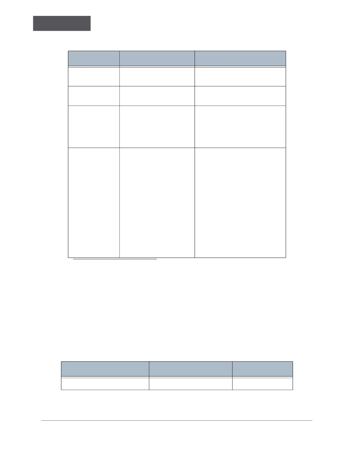
Table 2-5: Wetted Materials List
Module Part Material
Sample Inlet(s) Tube PTFE
Table 2-4: Valves List (Continued)
Valve Name Description

 Loading...