RELAY
. . . .. . . ... .... .... .... ..... ..
Sievers TOC-R3 Operation and Maintenance Manual
DLM 95000-01 EN Rev. A 146 © Veolia 2023
6. Use the Relay Configuration screen to build a Valid Relay Definition. When complete,
press the S
AVE Button.
• For example, to trigger the Relay on any Error, select the “FE” Condition. This will
energize the relay if the Analyzer reports an Error.
• For example, to report a “Healthy” status, select the “~ FE” Condition. This will de-
energize the relay if the Analyzer reports an Error.
7. Repeat this procedure for each Relay that needs to be configured.
8. The Analyzer will require a reboot to enable the new settings. Reboot the Analyzer.
For more information, see “To Reboot the Analyzer” on page 99.
M2 Stream 2 Online measurement active.
C1 Stream 1 calibration active.
C2 Stream 2 calibration active.
S1 Sample measurement with the settings of Stream
1 is active.
S2 Sample measurement with the settings of Stream
2 is active.
ON Analyzer is in Online Mode.
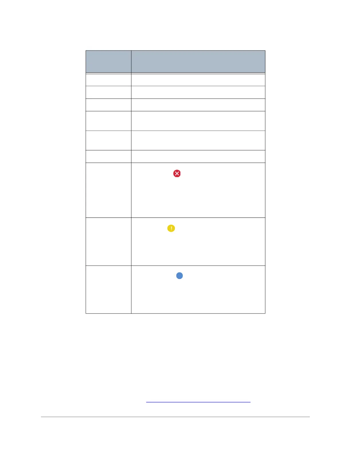
FE
Failure Error - This Condition Code refers to
the “E1” Error Codes, or Errors. This means a Red
Error and the system has stopped. This indicates
a critical error that affect instrument function. A
Failure Error must be acknowledged by the User
before the system can resume analysis. (Red)
ME
Main Error - This Condition Code refers to the
“E2” Error Codes, or Warnings. This system status
alert indicates an operational warning that can
affect the accuracy of the measurement results.
(Yellow)
WE
Warning Error - This Condition Code refers to
the “E3” Error Codes, or Maintenance Requests.
This is a notification to the User to schedule
upcoming required maintenance at the earliest
convenience. (Blue)
Table 4-6: Digital Relay Condition Codes and Descriptions, Short List (Continued)
Condition
Code
Explanation

 Loading...