EasyManua.ls Logo

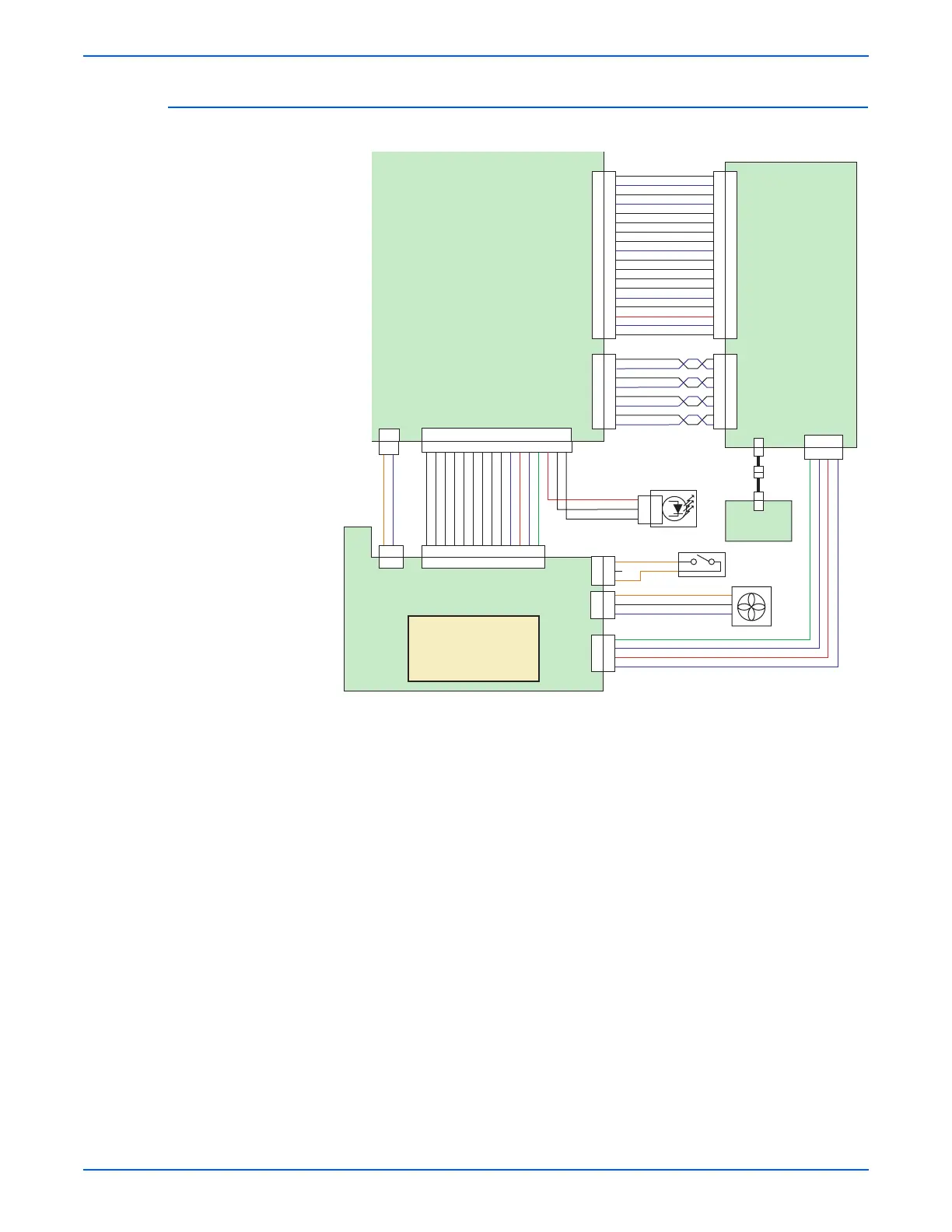
Xerox Phaser 6180 - Detailed Electrical Wiring Diagram (6 of 6)

Xerox Phaser 6180
616 pages
To Next Page IconTo Next Page
To Previous Page IconTo Previous Page
Loading...
Phaser 6180 Color Laser Printer Service Manual 10-27
Plug/Jack and Wiring Diagrams
Detailed Electrical Wiring Diagram (6 of 6)
CZ18 CZ18
CZ8 CZ8
VH2
CZ14
P15
J15
J502
P502
P14
J14
1
2
1
2
24V(AFT)
RTN
1
2
3
4
5
6
7
8
9
10
11
12
13
14
15
16
ALARM_FAN
xFAN_LOW
xFAN_STOP
24V_OFF
SLEEP
DEEP_SLEEP
LV_TYPE
FSR_ENB
xHEAT1
S.G.
3.3V
S.G.
5V
13
12
11
10
9
8
7
6
5
4
3
2
1
3.3V
xERASE_YMC
xERASE_K
3
2
1
P141
J141
Erase Lamp
P10
J10
P11
J11
J101
P101
J111
P111
(reserved)
S.G._IP
xBD
S.G._IP
xTOP_A_Y
xTOP_B_M
xTOP_C_C
xTOP_D_K
S.G._IP
xSRDY
xCRDY
xCMD
xSTS
S.G._IP
DEEP_SLEEP
3.3V_MOU
S.G._IP
xTEST_PRINT
1
2
3
4
5
6
7
8
9
10
11
12
13
14
15
16
17
18
18
17
16
15
14
13
12
11
10
9
8
7
6
5
4
3
2
1
8
7
6
5
4
3
2
1
Image
Processor
(IP) Board
1
2
3
4
5
6
7
8
xVDO_A_Y
S.G._IP
xVDO_B_M
S.G._IP
xVDO_C_C
S.G._IP
xVDO_D_K
S.G._IP
VH4
P401
J401
Control
Panel
OP_PANE
1
2
3
4
5V_IP
S.G._IP
3.3V_IP
L.G._IP
VH2
CZ13
VH3
VH4
CT3
P501
J501
P44
J44
P503
J503
P40
J40
24V Interlock
Switch
Side
Fan
1
2
3
1
2
3
1
2
3
4
24V
24V
24V_SIDE_FAN(BEF)
ALM_SIDE_FAN
RTN
s6180-495
MCU
Board
LVPS
24V Off: LV 24VOFF
Sleep:LV OFF
Deep Sleep: MCU OFF

Table of Contents

Other manuals for Xerox Phaser 6180

Related product manuals