10-16 Phaser 6280 Color Laser Printer Service Manual
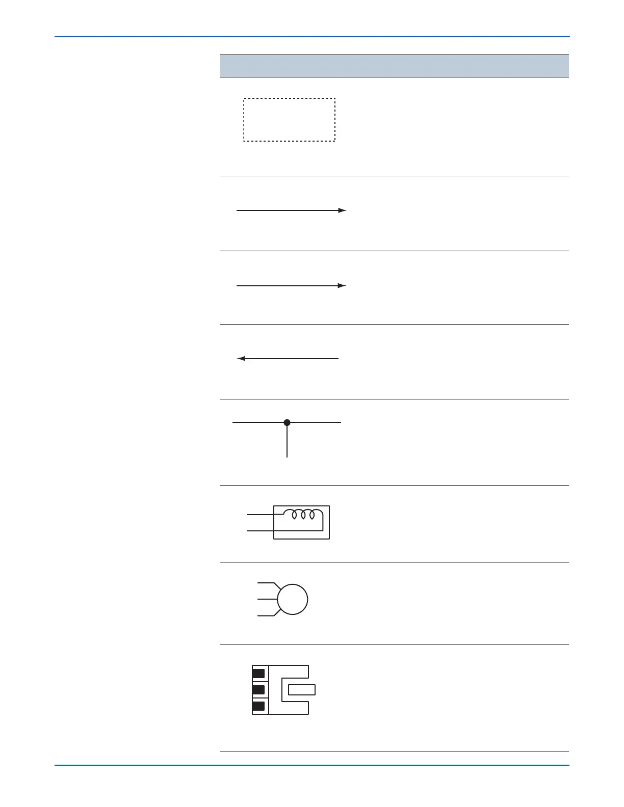
Plug/Jack and Wiring Diagrams
Denotes the control and its outline in the Board.
Denotes a connection between parts with
harness or wires, attached with signal name/
contents.
Denotes the function, and logic value of the
signal to operate the function (Low: L, High: H).
The given voltage is for signal in high status.
The arrow indicates the direction of signal.
Denotes the function, and logic value of the
signal when the function operated (Low: L, High:
H).
The given voltage is for signal in high status.
The arrow indicates the direction of signal.
Denotes a connection between wires.
Denotes a Clutch or Solenoid.
Denotes a Motor.
Denotes a Photo Sensor.
Symbol
Description
CLUTCH ON(L)+24V
Function Logic 1
EXIT SENSED(L)+3.3VDC
Function Logic 2
Optic Sensor

 Loading...


