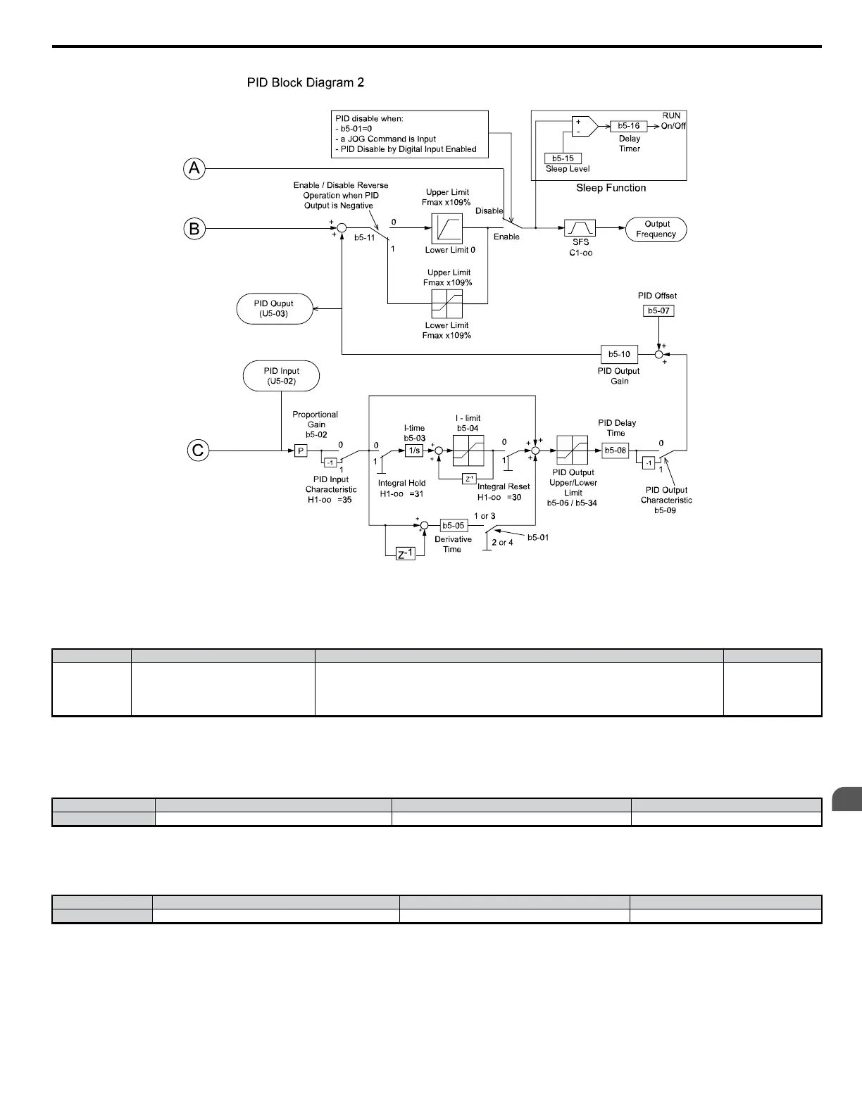
Figure 5.16 PID Block Diagram 2
n
b5-01: PID Function Setting
To enable PID control, select from settings 1 through 4.
No. Parameter Name Setting Range Default
b5-01 PID Function Setting
0: Disabled
1: D = Feedback
2: D = Feed-Forward
3: Frequency reference + PID output (D = Feedback)
4: Frequency reference + PID output (D = Feed-Forward)
0
n
b5-02: Proportional Gain Setting (P)
The proportional gain will apply a straight multiplier to the calculated difference (error) between the PID Setpoint and the measured transmitter feedback
at terminal A2. A large value will tend to reduce the error but may cause instability (oscillations) if too high. A small value may allow too much offset
between the setpoint and feedback.
No. Parameter Name Setting Range Default
b5-02 Proportional Gain Setting (P) 0.00 to 25.00 1.00
n
b5-03: Integral Time Setting (I)
The Integral factor of PID functionality is a time-based gain that can be used to eliminate the error (difference between the setpoint and feedback at steady
state). The smaller the integral time set into b5-03, the more aggressive the integral factor will be. To turn off the integral time, set b5-03 = 0.00.
No. Parameter Name Setting Range Default
b5-03 Integral Time Setting (I) 0.0 to 360.0 1.0 s
5.2 b: Setup
YASKAWA ELECTRIC SIEP C710606 18A YASKAWA AC Drive – V1000 Technical Manual (Preliminary)
125
5
Parameter Details

 Loading...


