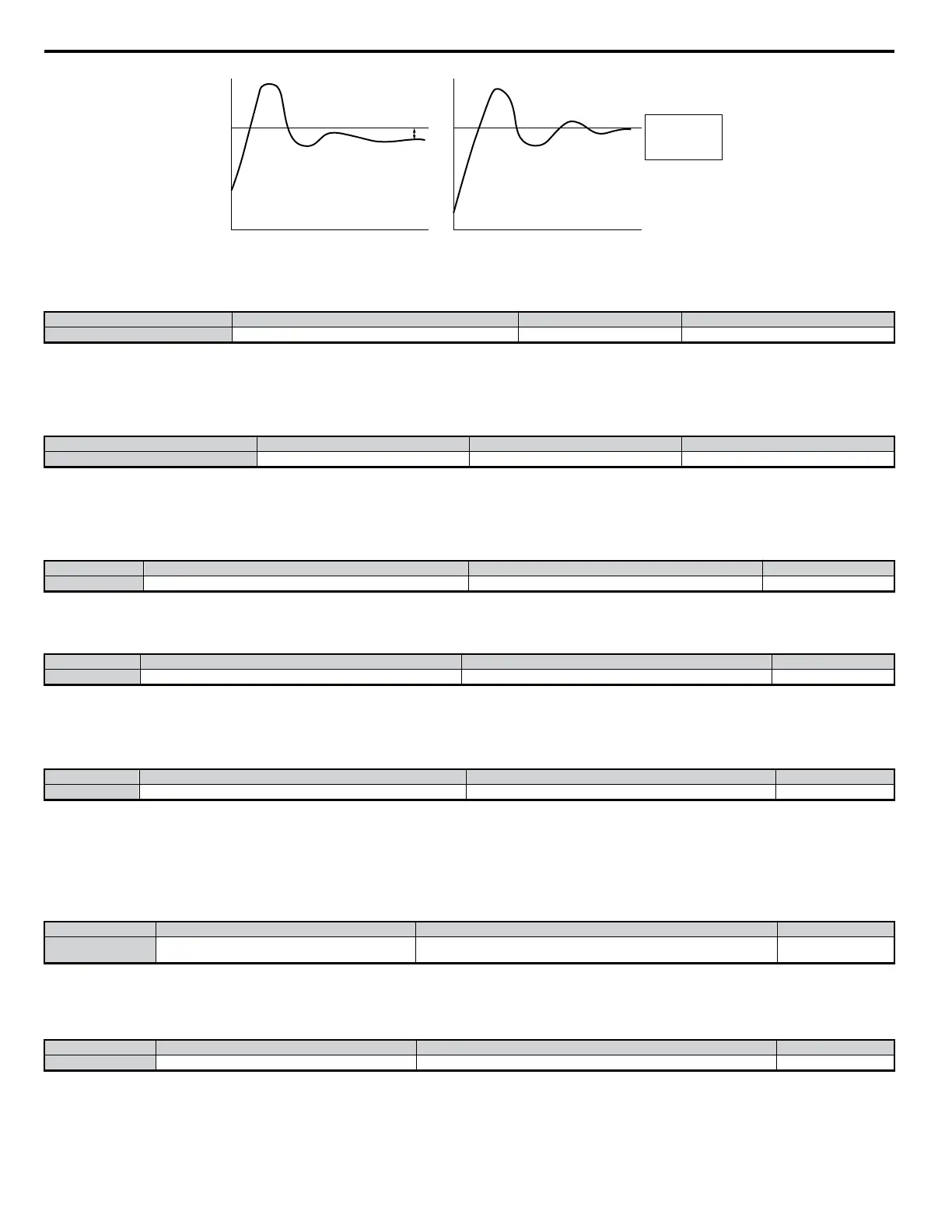
Zero
Offset with
Integral Action
No Intregral
With Intregral
Measured Feedback
Measured Feedback
Setpoint
Offset
Setpoint
Feedback
Feedback
TIME
TIME
n
b5-04: Integral Limit Setting
Sets the maximum output possible from the integrator. Set as a percentage of the maximum frequency (E1-04).
No. Parameter Name Setting Range Default
b5-04 Integral Limit Setting 0.0 to 100.0 100.0
Note: On some applications, especially those with rapidly varying loads, the output of the PID function may show a fair amount of oscillation. To suppress this oscillation, a limit
can be applied to the intrigue factor by programming b5-04.
n
b5-05: Derivative Time (D)
Adjust this parameter to increase the reponsiveness of the system.
No. Parameter Name Setting Range Default
b5-05 Derivative Time 0.00 to 10.00 0.00
Note: Try reducing this derivative time if overshoot occurs. Increase the derivative time to achieve stability faster even if overshoot occurs. Derivative control is disabled when this
value is set to 0.00.
n
b5-06: PID Output Limit
Sets the maximum output possible from the entire PID controller. Set as a percentage of the maximum frequency (E1-04).
No. Parameter Name Setting Range Default
b5-06 PID Output Limit 0.0 to 100.0 100.0
n
b5-07: PID Offset Adjustment
Sets the amount of offset of the output of the PID controller. Set as a percentage of the maximum frequency. The offset is summed with the PID output.
No. Parameter Name Setting Range Default
b5-07 PID Offset Adjustment -100.0 to 100.0 0.0
n
b5-08: PID Primary Delay Time Constant
Sets the amount of time for the filter on the output of the PID controller.
Normally, change is not required.
No. Parameter Name Setting Range Default
b5-08 PID Primary Delay Time Constant 0.00 to 10.00 0.00
Note: Effective in preventing oscillation when there is a fair amount of oscillation or when rigidity is low. Set to a value larger than the cycle of the resonant frequency. Increasing
this time constant reduces the drives responsiveness.
n
b5-09: PID Output Level Selection
Normally, the output of the PID function causes an increase in motor speed whenever the measured feedback is below the setpoint. This is referred to as
“direct acting response.” However, if b5-09 = “1: Reverse Output”, the output of the PID function causes the motor to slow down when the feedback is
below the setpoint. This is referred to as “reverse acting response.
No. Parameter Name Setting Range Default
b5-09 PID Output Level Selection
0: Normal Output (direct acting)
1: Reverse Output (reverse acting)
0
n
b5-10: PID Output Gain Setting
Applies a multiplier to the output of the PID function. Using the gain can be helpful when the PID function is used to trim the frequency reference.
Increasing b5-10 causes the PID function to have a greater regulating affect on the frequency reference.
No. Parameter Name Setting Range Default
b5-10 PID Output Gain Setting 0.00 to 25.00 1.00
n
b5-11: PID Output Reverse Selection
Determines whether reverse operation is allowed while using PID control (b5-01does not = 0) and the PID output goes negative.
5.2 b: Setup
126
YASKAWA ELECTRIC SIEP C710606 18A YASKAWA AC Drive – V1000 Technical Manual (Preliminary)

 Loading...


