Setting Descriptions
• L1-01 = 1
Set to “1” when using a general-purpose motor (standard motor). Because the motor is self-cooled, this setting lowers the overload tolerance as the
motor speeds up. The drive appropriately adjusts the electrothermal trigger point according to the motor overload characteristics, protecting the motor
from overheat throughout the entire speed range.
• L1-01 = 2
Use this setting when operating a inverter drive dedicated motor with a torque ratio of 1:10. Here, the drive runs the motor so that it produces constant
torque from 10% up to 100% speed. Slower speeds require torque derating.
• L1-01 = 3
Use this setting when operating a inverter drive dedicated motor with a torque ratio of 1:100. Here, the drive runs the motor so that is produces constant
torque from 1% up to 100% speed. Slower speeds require torque derating.
• L1-01 = 4
This setting is for operating a PM motor. IPM motors for derated torque have a self-cooling design, so the overload tolerance drops as motor slows.
Electrothermal operation is triggered in accordance with the motor overload characteristics, providing overheat protection across the entire speed range.
Note: Select a method to protect the motor from overheat by setting L1-01 between 1 and 4 when running a single motor from the drive. An external thermal relay is not needed.
NOTICE: Protect each motor with individual thermal overloads when multiple motors are connected to one drive. Failure to comply could result in improper drive operation. Disable
the electronic overload protection of the drive (L1-01= “0: Disabled”) and protect each motor with its own motor thermal overload.
DRIVE
power
supply
M1
MC1
MC1, MC2: magnetic contactors
L10, L20: thermal relays
L10
MC2 L20
M2
Figure 5.68 Example of Protection Circuit Design for Multiple Motors)
n
L1-02: Motor Overload Protection Time
Sets the time it takes the drive to detect motor overheat due to overload. This setting rarely requires adjustment, but should correlate with the motor
overload tolerance protection time for performing a hot start.
No. Name Setting Range Default Page
L1-02 Motor Overload Protection Time 0.1 to 5.0 1.0 min −
• Sets the operation time for electrothermal protection. This setting rarely needs to be changed.
• Defaulted to operate allow 150% overload operation for one minute.
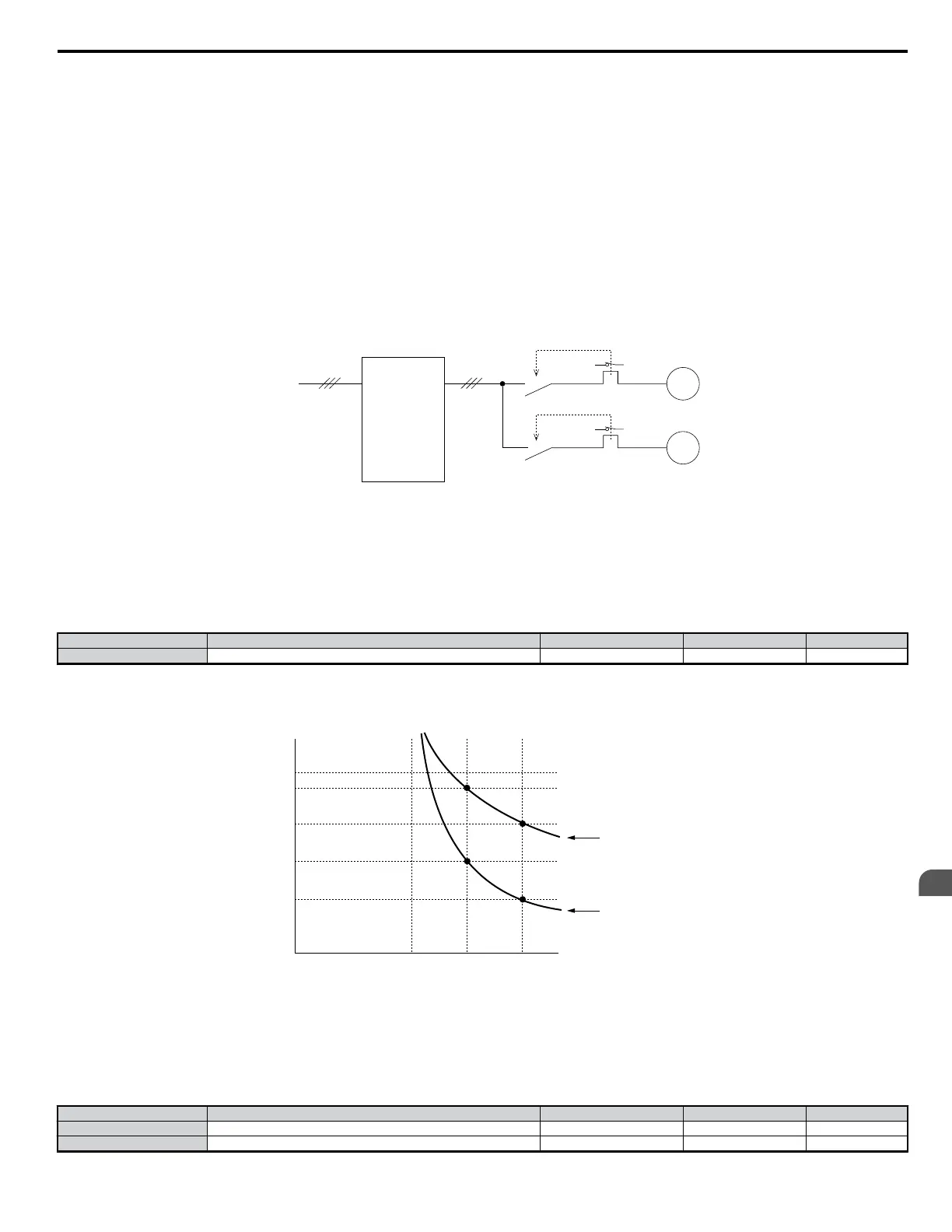
• Below is an example of the electrothermal protection operation time using a general-purpose motor operating at 60 Hz with L1-02 set to 1 minute.
Operation Time (minutes)
cold start
hot start
Motor Current (%)
E2-01 = 100% m o t o r c u r r e n t
10
7
3
1
0.4
0.1
0 100 150 200
Figure 5.69 Motor Protection Operation Time
Note: When the motor protection function is enabled (L1-01 is not set to 0), an OL1 alarm can be output through one of the multi-function outputs by setting H2-01 to 1F. The output
will close when the alarm is triggered at 90% overload.
n
L1-03: Motor Overheat Alarm Operation Selection L1-04: Motor Overheat Fault Operation Selection L1-05: Motor
Temperature Input Filter Time
The motor is protected from overheat by using a PTC thermistor embedded in the motor stator windings.
No. Name Setting Range Default Page
L1-03 Motor Overheat Alarm Operation Selection 0 to 3 3 −
L1-04 Motor Overheat Fault Operation Selection 0 to 2 1 −
5.8 L: Protection Functions
YASKAWA ELECTRIC SIEP C710606 18A YASKAWA AC Drive – V1000 Technical Manual (Preliminary)
187
5
Parameter Details

 Loading...


