No. Name Setting Range Default Page
L1-05 Motor Temperature Input Filter Time 0.00 to 10.00 0.20 sec −
Detailed Description
L1-03 and L1-04 determine how the motor is protected from overheat. Alarm OH3 and fault OH4 can be set to appear on the LED or LCD operator by
setting the motor temperature input filter time constant to parameter L1-04.
• L1-03 Settings
Setting Description
0 Ramp to Stop
1 Coast to Stop
2 Fast Stop (stops at the deceleration time set to C1-09)
3 Alarm Only (“oH3” flashes on the operator)
• L1-04 Settings
Setting Description
0 Ramp to Stop
1 Coast to Stop
2 Fast Stop (stops at the deceleration time set to C1-09)
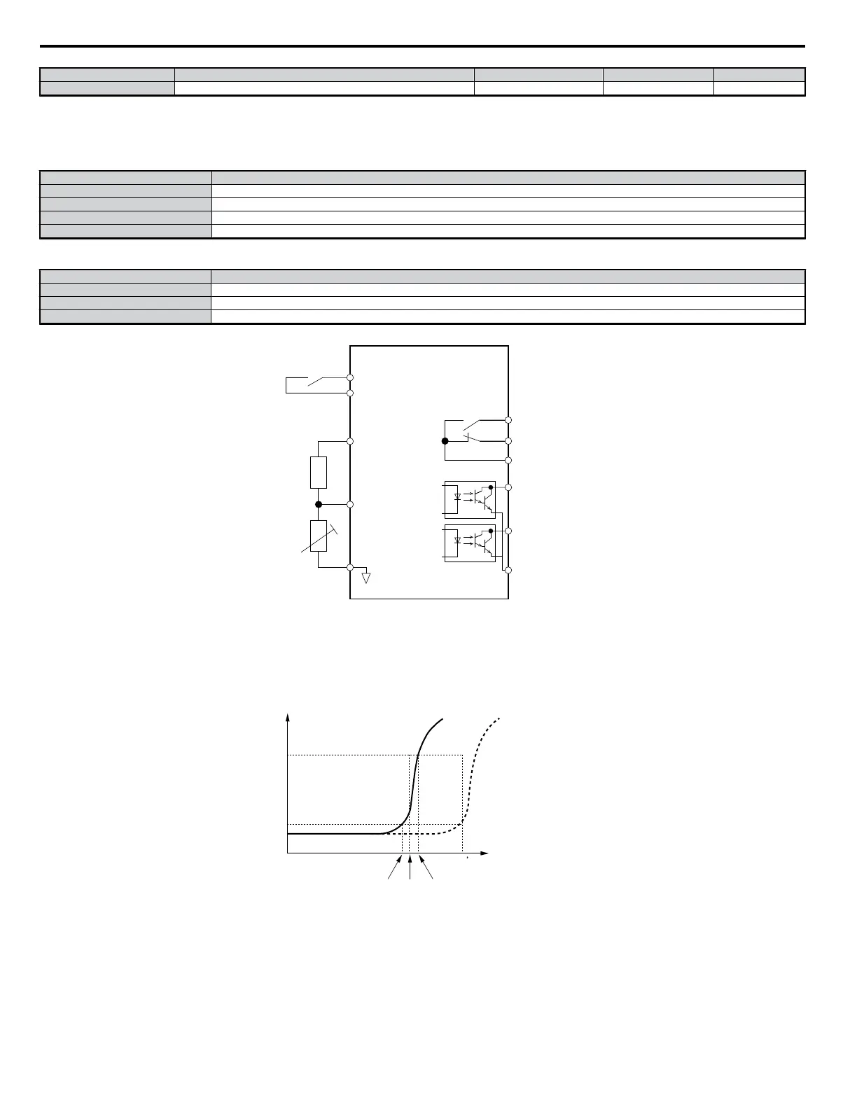
• Example Using PTC Thermistor
DRIVE
+V
(+10.5V, 20 mA)
multi-function input
branch
resistor
PTC
thermistor
MA
multi-function
output (contact)
multi-function
output (photo-coupler)
MB
MC
P1
P2
PC
A2 (0-10 V)
AC
Figure 5.70 Setting Up Motor Overheat Protection
Note: When using terminal A2, set DIP switch S1 to the voltage side.
PTC Thermistor Characteristics
The following diagram shows the characteristics of temperature and resistance on the PTC thermistor.
Class F
150°C
Class H
180°C
Resistance (W)
1330
Tr: threshold value
Temperature
Tr
Tr + 5
Tr
Tr - 5
550
Figure 5.71 PTC Thermistor Temperature: Resistance
5.8 L: Protection Functions
188
YASKAWA ELECTRIC SIEP C710606 18A YASKAWA AC Drive – V1000 Technical Manual (Preliminary)

 Loading...


