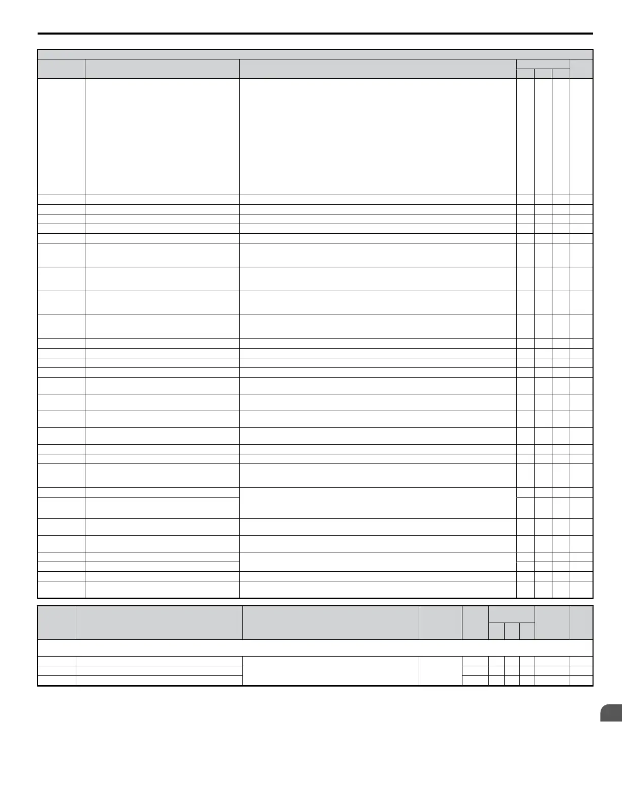
H1 Multi-Function Digital Input Selections
H1-o Setting
Function Description
Control Mode
Pg.
V/f OLV PM
20 to 2F External Fault
20: N.O., Always Detected, Ramp To Stop
21: N.C., Always Detected, Ramp To Stop
22: N.O., During Run, Ramp To Stop
23: N.C., During Run, Ramp To Stop
24: N.O., Always Detected, Coast To Stop
25: N.C., Always Detected, Coast To Stop
26: N.O., During Run, Coast To Stop
27: N.C., During Run, Coast To Stop
28: N.O., Always Detected, Fast-stop
29: N.C., Always Detected, Fast-stop
2A: N.O., During Run, Fast-stop
2B: N.C., During Run, Fast-stop
2C: N.O., Always Detected, Alarm Only (continue running)
2D: N.C., Always Detected, Alarm Only (continue running)
2E: N.O., During Run, Alarm Only (continue running)
2F: N.C., During Run, Alarm Only (continue running)
O O O —
30 PID Integral Reset Closed: Resets the PID control integral value. O O O —
31 PID Integral Hold Closed: Maintains the current PID control integral value. O O O —
32 Multi-Step Speed Reference 4 Used to select Multi-Step Speeds set in d1-01 to d1-16 O O O —
34 PID Soft Starter Closed: Disables the PID soft starter b5-17. O O O —
35 PID Input Switch Closed: Inverses the PID input signal O O O —
40 Forward Run Command (2-wire sequence)
Open: Stop
Closed: Forward run
Note: Can not be set together with Settings 42 or 43.
O O O —
41 Reverse Run Command (2-wire sequence)
Open: Stop
Closed: Reverse run
Note: Can not be set together with Settings 42 or 43.
O O O —
42 Run Command (2-wire sequence 2)
Open: Stop
Closed: Run
Note: Can not be set together with Settings 40 or 41.
O O O —
43 FWD/REV Command (2-wire sequence 2)
Open: Reverse
Closed: Forward
Note: Can not be set together with Settings 40 or 41.
O O O —
44 Offset Frequency 1 Addition Closed: Adds d7-01 to the frequency reference. O O O —
45 Offset Frequency 2 Addition Closed: Adds d7-02 to the frequency reference. O O O —
46 Offset Frequency 3 Addition Closed: Adds d7-03 to the frequency reference. O O O —
60 DC Injection Braking Command Closed: Triggers DC Injection Braking (b2-02) O O - —
61 External Search Command 1
Closed: Activates Current Detection Speed Search from the max. output frequency (E1-04) if
b3-01=0. Activates Speed Estimation Type Speed search if b3-01 =1.
O O O —
62 External Search Command 2
Closed: Activates Current Detection Speed Search from the frequency reference b3-01=0.
Activates Speed Estimation Type Speed search if b3-01 =1.
O O O —
65 KEB Ride-Thru 1 (N.C.)
Open: KEB Ride-Thru 1 enabled
Closed: Normal operation
O O O —
66 KEB Ride-Thru 1 (N.O.)
Open: Normal operation
Closed: KEB Ride-Thru 1 enabled
O O O —
67 Communications Test Mode Tests the MEMOBUS/Modbus RS-485/422 interface. O O O —
68 High-Slip Braking Closed: High-Slip braking is executed. Drive stops. O - - —
6A Drive Enable
Open: Drive disabled.
If this input is opened during run, then the drive will stop as specified by parameter b1-03.
Closed: Ready for operation.
O O O —
75 Up 2 Command Open: Maintains the current frequency reference
Closed: Increases or decreases the frequency reference.
UP 2 and Down 2 commands must be set in combination with each other. The frequency reference
source must be assigned to the operator (b1-01 = “0”).
O O O —
76 Down 2 Command O O O —
7A KEB Ride-Thru 2 (N.C.)
Open: KEB Ride-Thru 2 enabled
Closed: Normal operation
O O O —
7B KEB Ride-Thru 2 (N.O.)
Open: Normal operation
Closed: KEB Ride-Thru 2 enabled
O O O —
7C Short-Circuit Braking (N.O.)
Open: Normal operation
Closed: Short-Circuit Braking
- - O —
7D Short-Circuit Braking (N.C.) - - O —
7E Forward/Reverse Detection Direction of rotation detection (for Simple V/f w/PG) O - - —
9F DriveWorksEZ enable
Open: DWEZ enabled
Closed: DWEZ disabled
O O O —
No. Name Description Range Def.
Control
Mode
Addr.
Hex
Pg.
V/f
OL
V
PM
H2: Multi-Function Digital Outputs
Use H2 parameters to assign functions to the multi-function digital outputs.
H2-01 Terminal MA, MB and MC Function Selection (relay)
Refer to H2 Multi-Function Digital Output Settings on page
308 for a description of setting values.
0 to 192 <40>
E A A A 40B —
H2-02 Terminal P1 Function Selection (open-collector) 0 A A A 40C —
H2-03 Terminal P2 Function Selection (open-collector) 2 A A A 40D —
B.2 Parameter Table
YASKAWA ELECTRIC SIEP C710606 18A YASKAWA AC Drive – V1000 Technical Manual (Preliminary)
307
B
Parameter List

 Loading...


