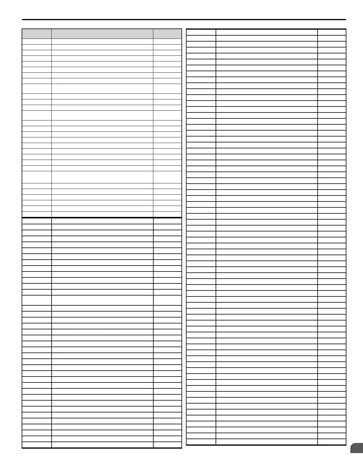
No. Name
User
Setting
L2-11
L3-01 Stall Prevention Selection during Accel.
L3-02 Stall Prevention Level during Accel.
L3-03 Stall Prevention Limit during Accel.
L3-04 Stall Prevention Selection during Deceleration
L3-05 Stall Prevention Selection during Run
L3-06 Stall Prevention Level during Run
L3-11 OV Suppression Function Selection
L3-17
Overvoltage Suppression and Deceleration Stall (Desired DC
Bus Voltage during Motor Stall)
L3-20 Main Power Circuit Voltage Adjustment Gain
L3-21 Accel/Decel Rate Calculation Gain
L3-22 Deceleration Time at Stall Prevention during Acceleration
L3-23
Automatic Reduction Selection for Stall Prevention during
Run
L3-24 Motor Acceleration Time for Inertia Calculations
L3-25 Load Inertia Ratio
L4-01 Speed Agreement Detection Level
L4-02 Speed Agreement Detection Width
L4-03 Speed Agreement Detection Level (+/-)
L4-04 Speed Agreement Detection Width (+/-)
L4-05 Frequency Reference Loss Detection Selection
L4-06 Frequency Reference at Reference Loss
L4-07 Frequency Detection Conditions
L5-01 Number of Auto Restart Attempts
L5-02 Auto Restart Operation Selection
L5-04 Fault Reset Interval Time
L5-05 Fault Reset Operation Selection
L6-01 Torque Detection Selection 1
L6-02 Torque Detection Level 1
L6-03 Torque Detection Time 1
L6-04 Torque Detection Selection 2
L6-05 Torque Detection Level 2
L6-06 Torque Detection Time 2
L6-08 Mechanical Weakening Detection Operation
L6-09 Mechanical Weakening Detection Speed Level
L6-10 Mechanical Weakening Detection Time
L6-11 Mechanical Weakening Detection Start Time
L7-01 Forward Torque Limit
L7-02 Reverse Torque Limit
L7-03 Forward Regenerative Torque Limit
L7-04 Reverse Regenerative Torque Limit
L7-06 Torque Limit Integral Time Constant
L7-07 Torque Limit Control Method Selection during Accel/Decel
L8-01
Internal Dynamic Braking Resistor Protection Selection
(ERF type)
L8-02 Overheat Alarm Level
L8-03 Overheat Pre-Alarm Operation Selection
L8-05 Input Phase Loss Protection Selection
L8-07 Output Phase Loss Protection
L8-09 Output Ground Fault Detection Selection
L8-10 Heatsink Cooling Fan Operation Selection
L8-11 Heatsink Cooling Fan Operation Delay Time
L8-12 Ambient Temperature Setting
L8-15 OL2 Characteristics Selection at Low Speeds
L8-18 Soft CLA Selection
L8-19 Frequency Reduction Rate during OH Pre-Alarm
L8-29 Current Unbalance Detection (LF2)
L8-35 Side-by-Side Selection
L8-38 Carrier Frequency Reduction
L8-41 Current Alarm Selection
n1-01 Hunting Prevention Selection
n1-02 Hunting Prevention Gain Setting
n1-03 Hunting Prevention Time Constant
n1-05 Hunting Prevention Gain while in Reverse
n2-01 Speed Feedback Detection Control (AFR) Gain
n2-02 Speed Feedback Detection Control (AFR) Time Constant
n2-03 Speed Feedback Detection Control (AFR) Time Constant 2
n3-01 High-Slip Braking Deceleration Frequency Width
n3-02 High-Slip Braking Current Limit
n3-03 High-Slip Braking Dwell Time at Stop
n3-04 High-Slip Braking Overload Time
n3-13 Overexcitation Deceleration Gain
n3-21 High-Slip Suppression Current Level
n3-23 Overexcitation Operation Selection
n6-01 Line-to-Line Motor Resistance Online Tuning
n8-45 Speed Feedback Detection Control Gain
n8-47 Pull-In Current Compensation Time Constant
n8-48 Pull-In Current
n8-49 Load Current
n8-50 Heavy Load Current Level (for PM)
n8-51 Acceleration Time Pull-In Current
n8-55 Load Inertia
n8-56 High Performance Control Selection
o1-01 Drive Mode Unit Monitor Selection
o1-02 User Monitor Selection After Power Up
o1-03 Digital Operator Display Selection
o1-05 LED Contrast
o1-10 Frequency Reference Setting and User-Set Display
o1-11 Frequency Reference Setting / Decimal Display
o2-01 LOCAL/REMOTE Key Function Selection
o2-02 STOP Key Function Selection
o2-03 User Parameter Default Value
o2-04 Drive/kVA Selection
o2-05 Frequency Reference Setting Method Selection
o2-06 Operation Selection when Digital Operator is Disconnected
o2-07 Motor Direction at Power Up when Using Operator
o3-01 Copy Function Selection
o3-02 Copy Allowed Selection
o3-03 Copy Mode Selection
o4-01 Accumulated Operation Time Setting
o4-02 Accumulated Operation Time Selection
o4-03 Cooling Fan Maintenance Setting (Operation Time)
o4-05 Capacitor Maintenance Setting
o4-07 Inrush Prevention Relay Maintenance Setting
o4-09 IGBT Maintenance Setting
o4-10 IGBT Maintenance Setting
o4-11 U2, U3 Initial Value Selection
o4-12 kWH Monitor Initial Value Selection
o4-13 Motor r/min Reset
r1-01 DWEZ Connection Parameter 1 (upr.)
r1-02 DWEZ Connection Parameter 1 (lwr.)
r1-03 DWEZ Connection Parameter 2 (upr.)
r1-04 DWEZ Connection Parameter 2 (lwr.)
r1-05 DWEZ Connection Parameter 3 (upr.)
r1-06 DWEZ Connection Parameter 3 (lwr.)
r1-07 DWEZ Connection Parameter 4 (upr.)
r1-08 DWEZ Connection Parameter 4 (lwr.)
r1-09 DWEZ Connection Parameter 5 (upr.)
r1-10 DWEZ Connection Parameter 5 (lwr.)
r1-11 DWEZ Connection Parameter 6 (upr.)
r1-12 DWEZ Connection Parameter 6 (lwr.)
r1-13 DWEZ Connection Parameter 7 (upr.)
r1-14 DWEZ Connection Parameter 7 (lwr.)
r1-15 DWEZ Connection Parameter 8 (upr.)
r1-16 DWEZ Connection Parameter 8 (lwr.)
r1-17 DWEZ Connection Parameter 9 (upr.)
r1-18 DWEZ Connection Parameter 9 (lwr.)
r1-19 DWEZ Connection Parameter 10 (upr.)
r1-20 DWEZ Connection Parameter 10 (lwr.)
r1-21 DWEZ Connection Parameter 11 (upr.)
r1-22 DWEZ Connection Parameter 11 (lwr.)
r1-23 DWEZ Connection Parameter 12 (upr.)
r1-24 DWEZ Connection Parameter 12 (lwr.)
r1-25 DWEZ Connection Parameter 13 (upr.)
r1-26 DWEZ Connection Parameter 13 (lwr.)
r1-27 DWEZ Connection Parameter 14 (upr.)
r1-28 DWEZ Connection Parameter 14 (lwr.)
r1-29 DWEZ Connection Parameter 15 (upr.)
r1-30 DWEZ Connection Parameter 15 (lwr.)
D.5 User Setting Table
YASKAWA ELECTRIC SIEP C710606 18A YASKAWA AC Drive – V1000 Technical Manual (Preliminary)
359
D
Standards Compliance

 Loading...


