Configuring VLAN Translation Introduction
4-209
Software Reference for SwitchBlade x3100 Series Switches (Layer Two Switching)
• There is a one-to-one mapping between the customer VLAN ID and the VLAN ID used for crossing the net-
work operator network. (Each customer VLAN ID can be translated into only one VLAN ID, and vice
versa.)
• The customer VLANs to be translated must be tagged.
4.10.5.3 Configuration Procedure
The following procedure shows the commands used to provision and deprovision VLAN translations based on
Figure 4-27.
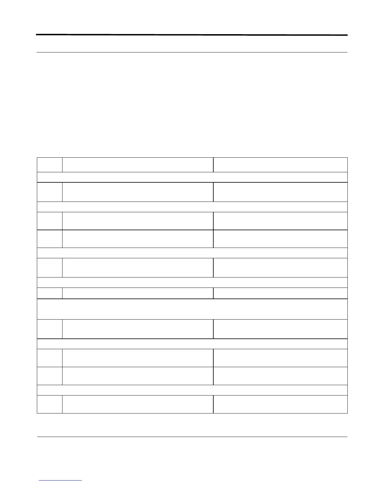
TABLE 4-32 Configuration procedure for VLAN Translation
Step Command Description
Configure System A
1
CREATE VLAN=VLAN100 VID=100
CREATE VLAN=VLAN200 VID=200
Add interfaces to the VLANs
2
ADD VLAN=100 INTERFACE=0.1,0.2,2.0
FRAME=TAGGED
3
ADD VLAN=200 INTERFACE=0.1,0.2,2.1
FRAME=TAGGED
Set the translation option on interface 2.0
4
SET VLAN=100 INTERFACE=2.0 TRANS-
LATE=10
Translate the Customer A VLAN ID 10 to
100.
s
Set the translation option on interface 2.1
5
SET VLAN=200 INTERFACE=2.1 TRANSLATE=10 Translate the Customer B VLAN ID 10 to 200.
Configure System E
Create the VLANs
6
CREATE VLAN=VLAN100 VID=100
CREATE VLAN=VLAN200 VID=200
Add interfaces to the VLANs
7
ADD VLAN=100 INTERFACE=0.0,3.0
FRAME=TAGGED
8
ADD VLAN=200 INTERFACE=0.0,3.1
FRAME=TAGGED
Set the translation option on interface 3.0
9
SET VLAN=100 INTERFACE=3.0 TRANS-
LATE=10
Translate the Customer A VLAN ID 10 to 100

 Loading...


