Configuring ARP Introduction
6-155
Software Reference for SwitchBlade x3100 Series Switches (Access and Security)
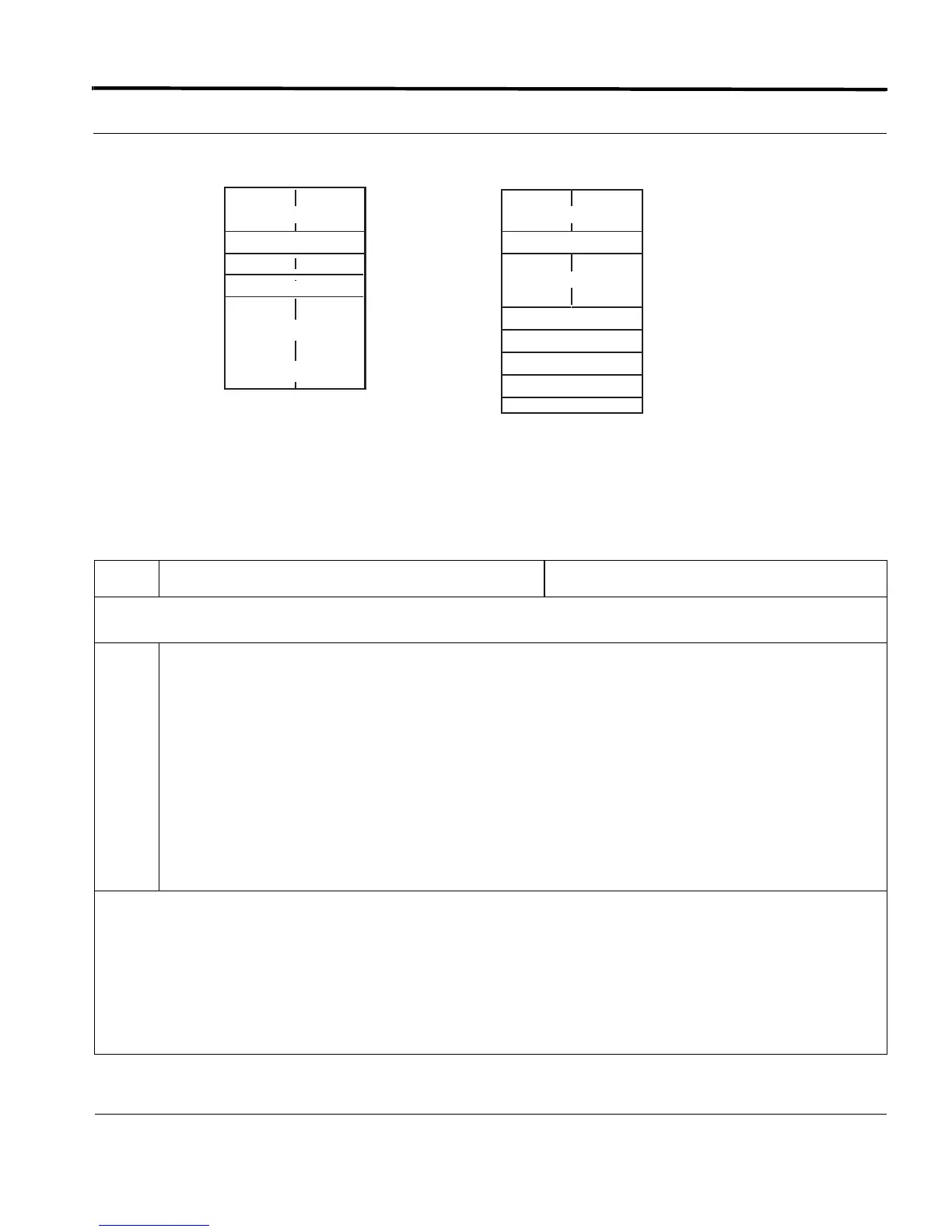
FIGURE 6-5 ARP filtering
The following procedure shows the commands used to set up ARP on an interface.
TABLE 6-24 Configuration Procedure for ARP
Step Command Description
Add a IP filter for ‘X’ in Figure 6-5. Deny all other IP packets. Note that ARP filtering is not enabled, so ARP and any
other non-IP packets can pass
1.
officer SEC> CREATE ACCESSLIST=iparpfilt RULE=DENY IPSOURCE=192.168.1.0
SOURCEMASK=255.255.255.0
officer SEC> ADD ACCESSLIST=iparpfilt INTERFACE=17.4
officer SEC> SHOW ACCESSLIST ALL
--- Access Lists -----------------------------------------------------
Name Interfaces Rule Action Fields
---------------- ---------------- ---- ------- ---------------------------
----
iparpfilt ETH:17.4 1 DENY IPSOURCE=192.168.1.0
SOURCEMASK=255.255.255.0
-- PERMIT
At this point, IP addresses in the range 192.168.1.0 through 192.168.1.255 are now being specified.
With the IPSOURCE as "192.168.1.0" with the SOURCEMASK=255.255.255.0, the first 24 bits are being filtered. so
addresses from 192.168.1.0 through 192.168.1.255 will be blocked because of the DENY rule. The PERMIT would allow
packets not filtered by the DENY rule.)
The user should keep in mind, however, that ARP packets are still passing through because they have not been specifically
blocked.
Enable the ARP filtering.The system now filters ARP packets so that only the IP address for ‘X’ in Sender L3 Addr. passes.
0x800
X
IP
0x806
X
ARP
IP Source
MAC Src. Addr.
Y
MAC Dest. Addr.
Sender L3 Addr.
Sender L2 Addr.
Target L3 Addr.
Target L2 Addr.

 Loading...


