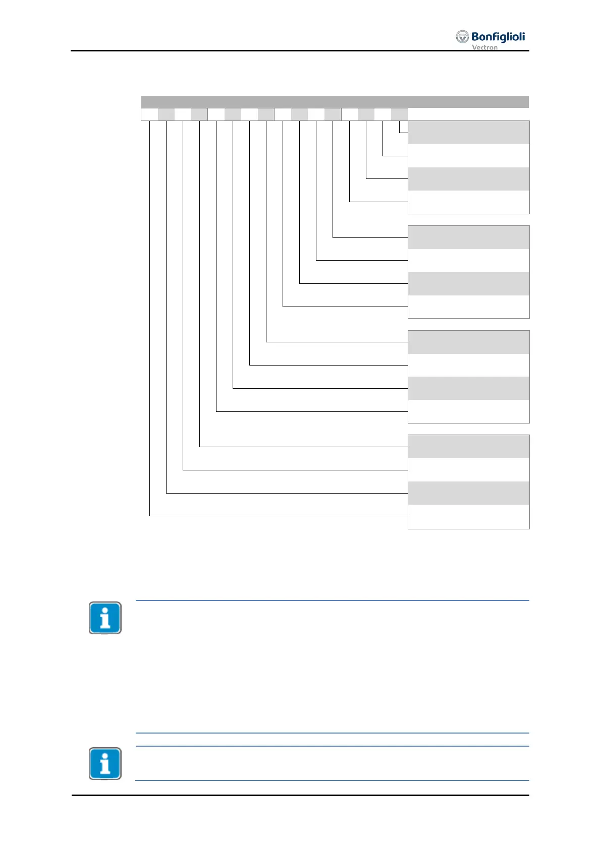
Ready to switch on
Switched on
Operation enabled
Fault
Voltage enabled
Quick stop (Low active)
Switch on disabled
Warning
Manufacturer specific
9
Remote
Target reached
Internal limit active
Operation mode specific
Operation mode specific
Manufacturer specific
Manufacturer specific
Warning 2
Status word
bits 12 and 13
operation mode specific
are used in motion control configu-
rations (p.30 = x40) only.
ACTIVE CUBE inverters support an external 24V supply for control logic. Even if the
mains are not switched on, communication between the PLC and the inverter can still
be established.
Bit 4 “Voltage enabled” of the
Status word
indicates the current state of the mains
power supply.
Bit 4 “Voltage enabled” = 0
signals “no mains voltage” and the state transition
“Ready to switch on” “Switched on” is not possible.
Bit 4 “Voltage enabled” = 1 signals “mains voltage switched on” and the state trans
i-
tion “Ready to switch on” “Switched on” is possible.
ACTIVE CUBE inverters and ACTIVE inverters can show different states, because bit 4
of the Status word is used additionally in ACTIVE CUBE like described above.
04/13 CM-CAN ACU 169

 Loading...


