Electrical dangers
DANGER!
Electrical hazards are marked by the symbol opposite.
W
ork in these areas may only be carried out by trained personnel with the
appropriate authorisation.
7.1 Initial start-up of the ‘EcoPro’
The enabled viscosity (high or low) is indicated by an LED display when the
pump is switched on.
Meaning of the LED colours:
n LED - Metering mode "low" (left):
–
Permanently on when the pump is started, colour: green (standby).
– Flashing when operated in "low" metering mode, colour: yellow.
n
LED - Metering mode "high" (right):
–
Flashing when operated in "high" metering mode, colour: yellow.
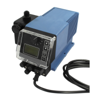
Fig. 16: EcoPro control elements ‘’
1 Rotary button for stroke adjustment
2 Locking mechanism for fixing the rotary button in place
3 LED - Alarm signal, colour: red flashing
4 LED - Dosing mode "low", colour: yellow
LED - When the pump is started: green (standby)
5 LED - Dosing mode "high", colour: flashing yellow
6
‘ON/OFF button’
7 Test button
8 Cable bushing for the mains connection cable
1. Install the mounting plate and pump in the required location and installation scenario.
Ä
Chapter 6.2 ‘Assembly variants’ on page 31
2. Make the hydraulic connections.
Ä
Chapter 6.3.1 ‘Hydraulic installation’ on page 34
3. If necessary
, make the electrical connections for signal inputs.
Ä
Chapter 6.3.4 ‘Electrical Installation’ on page 42
4. Connect the mains plug (fitted at the factory) to the power supply
.
5.
Switch on the pump with the ‘ON/OFF button’ .
6. Reset the viscosity by pressing the ‘ON/OFF’ and ‘T
est’
buttons simultaneously (for approximately 3 seconds).
ð
The LED that corresponds to the selected viscosity briefly flashes green (Fig. 16).
7.
Switch on the pump by pressing the ‘ON/OFF button’ .
ð
The pump resumes operation and the LED for the new viscosity setting flashes
(Fig. 16
).
8. Perform calibration on initial start-up:
Ä
Chapter 7.4 ‘Calibration on initial start-up’ on page 48
Start-up
45 417102264 Rev. 5-01.2019