5 Description of the pump
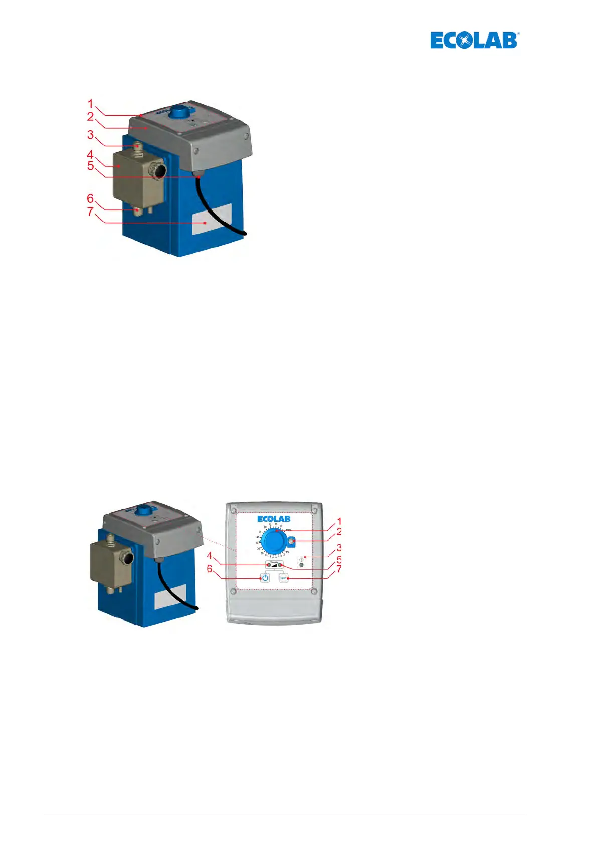
Fig. 3: Construction ‘EcoPro’
1 Operator panel
2 Rotary operating device
3 Pressure connection / pressure valve
4 Pump head
5 Mains cable bushing / mains power supply
6 Suction connection / suction valve
7 Position of type plate
5.1 Identification of the pump - Type plates
The pump is equipped with a type plate which provides the pump-specific data for
identification.
The type plate is located on the underside of the pump at the front (
Fig. 3, 7) and is
explained in the
Ä
Chapter 13.2 ‘Equipment marking / Type plate’ on page 74.
5.2 Control elements ‘EcoPro’
Fig. 4: Control elements ‘EcoPro’
1 Rotary button for stroke adjustment
2 Locking mechanism for fixing the rotary button in place
3 LED - alarm signal, colour: red flashing
4 LED - dosing mode "low", colour: Yellow
LED - when starting the pump: Green (standby)
5 LED - Dosing mode "high", colour: Yellow flashing
6 On/off switch
7 Test button
8 Cable bushing for the mains connection cable
Description of the pump
26417102264 Rev. 5-01.2019