8.2 Setting of the capacity / flow rate
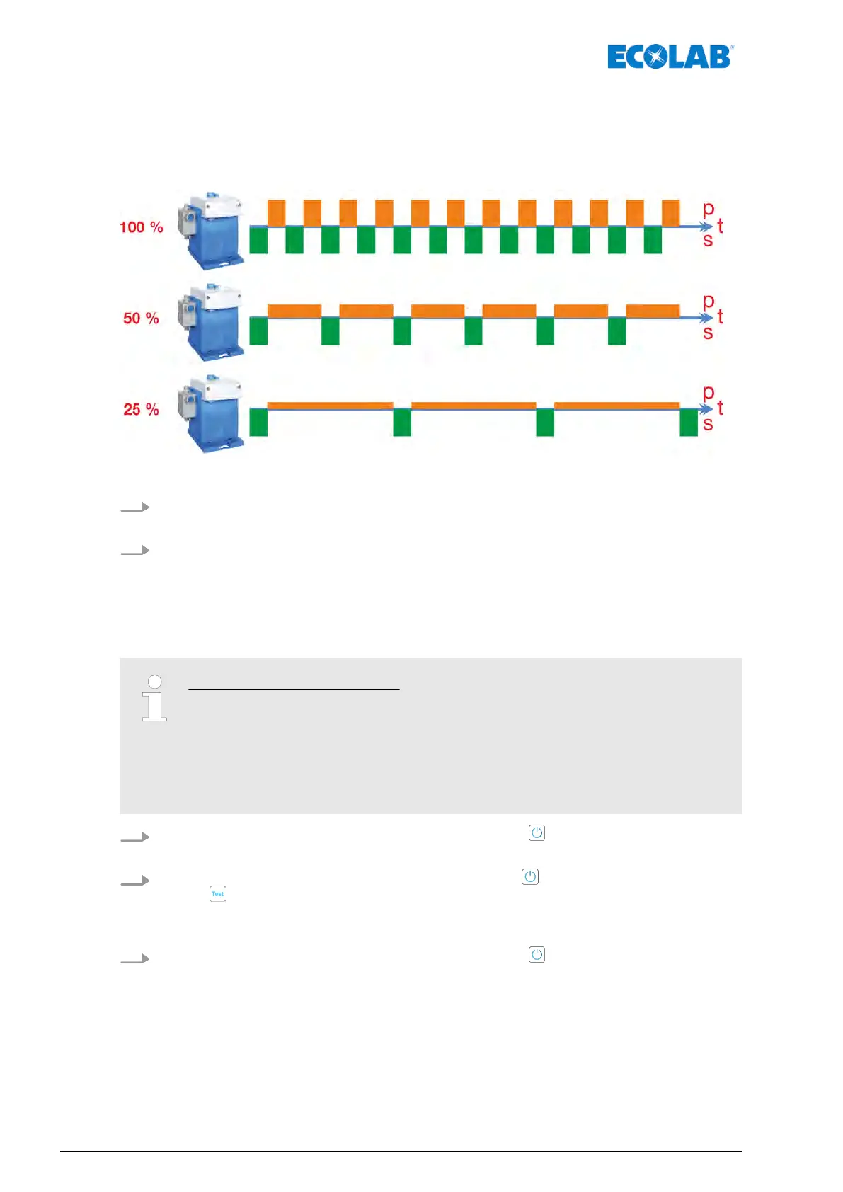
The stepper motor technology means that both the suction stroke duration and metering
stroke duration can be set separately during operation via the stroke adjustment
(Fig. 18
, pos. 1).
Fig. 19: Time distribution (t) of the suction (s) and metering stroke (p) at a metering rate setting of 100, 50 and 25%
1. Use the‘rotary button for stroke adjustment’ (Fig. 18, 1) to set the required capacity /
flow rate.
2. Locking mechanism to fix the rotary button in place (
Fig. 18, 2) should be tightened
using a suitable screwdriver to exclude the risk of accidental adjustment.
8.3 Setting / changeover of the viscosity
Meaning of the LED colours:
– LED - Metering mode "low" (left): Fig. 18, 4.
– Permanently on when the pump is started, colour: green (standby).
– Flashing when operated in "low" metering mode, colour: yellow
.
– LED - Metering mode "high" (right): Fig. 18, 5.
– Flashing when operated in "high" metering mode, colour: yellow.
1.
Switch of
f the pump by pressing the ‘ON/OFF button’
(Fig. 18, 6).
ð
The pump stops operating, and all the LEDs go out.
2.
Reset the viscosity by pressing the ‘ON/OFF button’ (Fig. 18, 6) and the ‘T
est
button’
(Fig. 18, 7) simultaneously for approximately 3 seconds.
ð
The associated LED (low = left
Fig. 18, 4, high = right, Fig. 18, 5) flashes green
briefly.
3.
Switch of
f the pump by pressing the ‘ON/OFF button’
(Fig. 18, 6).
ð
The pump starts and the LED for the newly set viscosity flashes.
Operation
50417102264 Rev. 5-01.2019