6.3 Installation
Some of the graphics shown in this chapter are schematic diagrams which are
intended to represent the general installation. The installation examples and
applications shown here are of a functional nature. They provide an overview
of correct forms of installation, or approaches to be avoided, in order to ensure
that it works properly
.
6.3.1 Hydraulic installation
Personnel:
n
Mechanic
n
Service personnel
n
Specialist
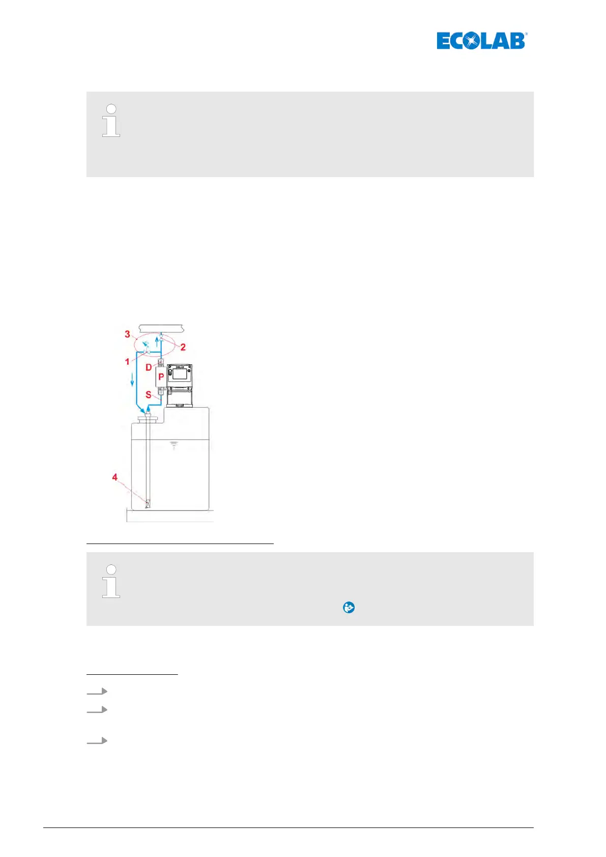
Installation diagram:
1 Overflow valve
2 Pressure control valve
3 Option: Multi-function valve (MFV)
4 Suction lance or floor suction valve
D Pressure valve
P Pump head
S Suction valve
Using a multi-function valve (MFV):
Dosing, pressure retention and overpressure valves (pos. 1 and pos. 2) can be
replaced by a multifunction valve (MFV) (pos. 3) from our product range, which
combines all these functions. When using a multifunction valve, it is essential
to observe the corresponding instructions .
When using a metering valve, metering spikes < 1.2 mPa (12 bar) may occur.
This means that the pump displays an error and stops.
Troubleshooting:
1. Check back-pressure!
2. Check all valves on the metering lines; it may be that a valve fitted in the metering
line is not opening correctly or may even be closed.
3. Check the system pressure, and reduce if necessary
.
Assembly, installation, modification and upgrades
34417102264 Rev. 5-01.2019