6.3.4 Electrical Installation
Personnel:
n
Qualified electrician
To allow the connection of a cable for pulse control, a M 12 x 1.5 screw
coupling is included with the pump.
The mains cable is already installed at the factory
.
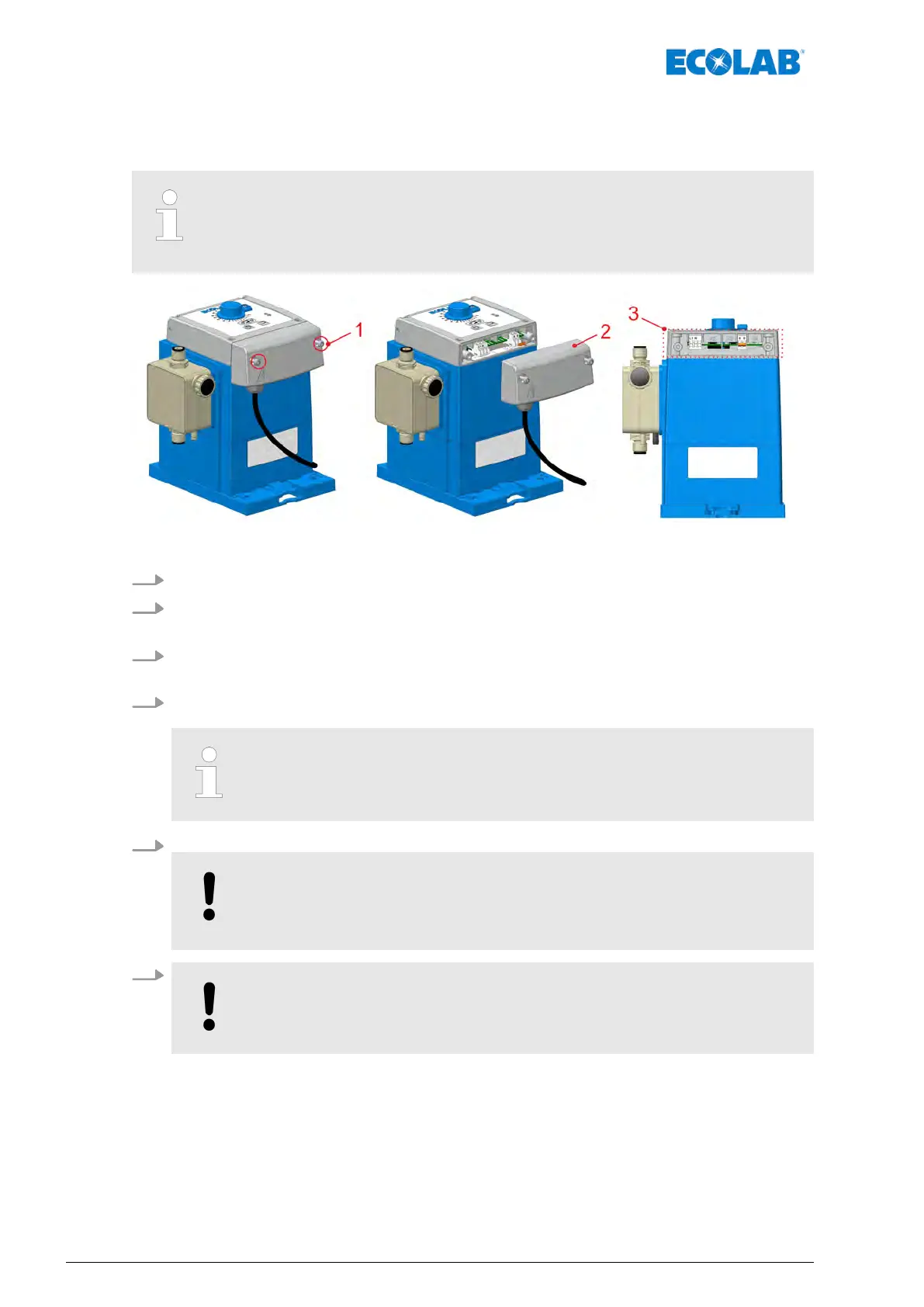
Fig. 14: EcoPro electrical Installation ‘’
1. Remove both housing screws. These are secured to prevent them falling out.
2. Remove the front cover
.
ð
The PCB for the electrical connection is exposed.
3. T
o connect an external enable signal, route the connector lines through the threaded
cable union.
4. Perform the electrical installation for the external enable signal:
Ä
Chapter 6.3.4.1 ‘Terminal assignment - External enable signal’ on page 43.
Permissible external diameters for connecting the inputs/outputs:
AD Ø = 5.1-5.7 mm (pos. 2-5).
Permissible cable: LIYY 4x0.5; LIYY 5x0.34; L
YCY 2x0.34; Oilflex 4x0.5
5. After electrical installation has been completed, fit the cover back onto the housing.
NOTICE!
Make sure that the seal is free of dirt to ensure that it seals the system
properly
.
6.
NOTICE!
Tighten both housing screws "handtight".
Assembly, installation, modification and upgrades
42417102264 Rev. 5-01.2019