9.3 Triggering by Analog Signals
157
9
Chapter 9 Trigger Settings
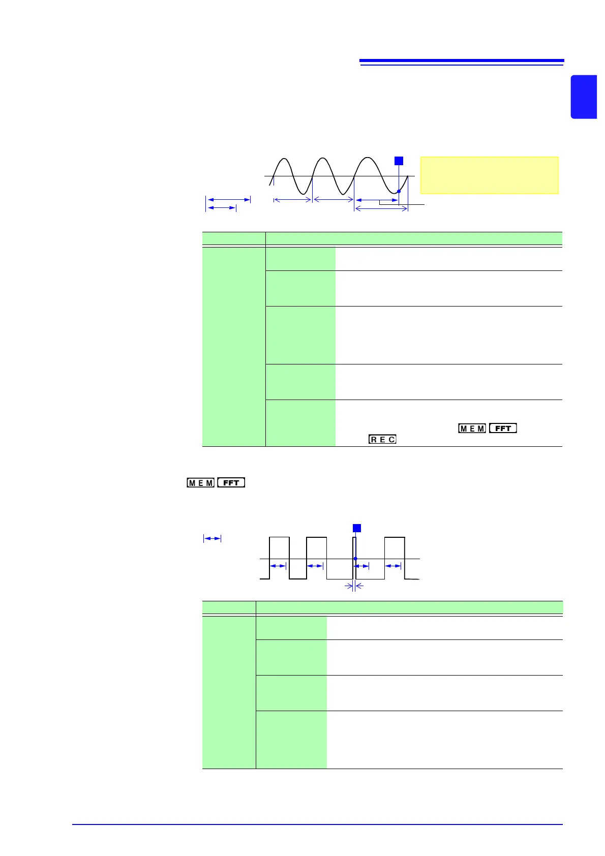
4. In-Period Trigger, Out-of-Period Trigger __________________________
The rising edge and falling edge cycle of the reference voltage is measured, and
triggering occurs when the cycle enters the preset range (In) or leaves the preset
range (Out).
See: "Description" ( p.159)
*1: Changes in sync with the time axis range.
5. Glitch Trigger( only)___________________________________
Triggering occurs when the input signal crosses the trigger level (threshold volt-
age) if its pulse width is shorter than the specified width.
Type Parameters
[Per.I]
or
[Per.O]
[L] (Level) Sets the level (voltage value) for the trigger. (The setting
can be made in 1/50 increments.)
[S] (Slope) Determines whether triggering occurs when the signal
crosses the threshold (trigger level) on the upslope (ris-
ing edge) or on the downslope (falling edge). (↑, ↓)
[P ↓]
(Period lower
limit)
*1
Available settings are 0 and more than 5 times the sam-
pling frequency. Settings higher than the upper limit val-
ue are not accepted. (When the setting is 0, the lower
limit is disregarded, and triggering occurs only on the
upper limit.)
[↑]
(Period upper
limit)
*1
The setting range extends to 20,000 times the sampling
frequency. Lower settings than the lower limit value are
not accepted.
[F] (Filter) Triggering occurs when the trigger criteria are met with-
in the specified filter width. This is useful to prevent spu-
rious triggering due to noise. ( : Off, 0.1 -
10 div, : Off, On*) *: Filter width is 10 ms.
Within Period
Range
Out of Period Range
T
Reference
Voltage Level
Period Upper Limit
Period Upper Threshold
Period Lower Limit
About the Trigger Point
The trigger point occurs one sam-
ple after the criterion is met.
Type Parameters
[Grit.]
[L] (Level) Sets the level (voltage value) for the trigger. (The setting
can be made in 1/50 increments.)
[S] (Slope) Determines whether triggering occurs when the signal
crosses the threshold (trigger level) on the upslope (rising
edge) or on the downslope (falling edge). (↑, ↓)
[Event]
The number of signal rising edge (or falling edge) events
is counted, and triggering occurs when the Event number
set here is exceeded. (1 to 4000)
[Width] Sets the pulse width (time) that is used to determine a
glitch. Triggering occurs when the width is lower than this
value. (The available setting range depends on the sam-
pling frequency. Lower limit: sampling frequency x 2, up-
per limit: sampling frequency x 4000)
Glitch Width
Trigger Level
Input Waveform
Trigger Slope: [
↑ ]
T