315
• X.25 virtual circuit range
The X.25 protocol can create multiple logical virtual connections over a physical link between
DTE and DCE. These virtual connections are called virtual circuits or logical channels. Up to
4095 virtual circuits can be established by X.25, and the virtual circuit number is in the range of
1 to 4095. The number used to differentiate each virtual circuit (or logical channel) is called LCI
or VCN.
Strictly speaking, virtual circuits and logical channels are different. However, at the user end,
they are not distinguished strictly.
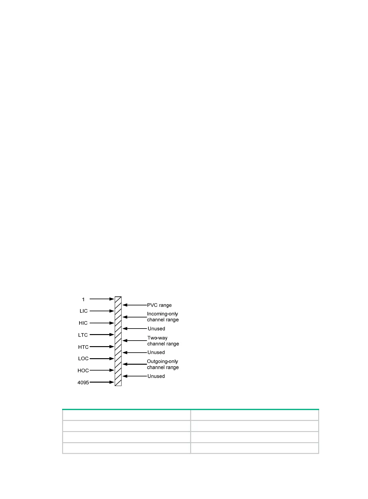
An important part of X.25 operation is how to manage the total 4095 virtual circuits.
All the virtual circuit numbers are divided into the following ranges (listed here in ascending
order):
{ A—Permanent virtual circuits (PVCs) range.
{ B—Incoming-only channel range.
{ C—Two-way channel range.
{ D—Outgoing-only channel range.
The numbers of the virtual circuits established by an X.25 call must be set in the ranges of B, C,
and D. The permanent virtual circuits must be set in the A range.
According to ITU-T Recommendation X.25, the idle channel allocation rules in initiating calls
are as follows:
{ Only the DCE can initiate a call using a channel in the incoming-only channel range.
{ Only the DTE can initiate a call using a channel in the outgoing-only channel range.
{ Both the DCE and the DTE can initiate a call using a channel in the two-way channel range.
{ DCE always uses the lowest available logical channel.
{ DTE always uses the highest available logical channel.
You can avoid the case that one side of the communication occupies all the channels, and
minimize the possibility of call collision.
As shown in Figure 124, in the X.25 protocol, six pa
rameters are employed to define the four
ranges.
Figure 124 X.25 channel delimitation
Table 4 X.25 channel range delimitation parameters
Parameter Description
LIC Lowest Incoming-only Channel.
HIC Highest Incoming-only Channel.
LTC Lowest Two-way Channel.

 Loading...


