306
MSTP configuration example
Network requirements
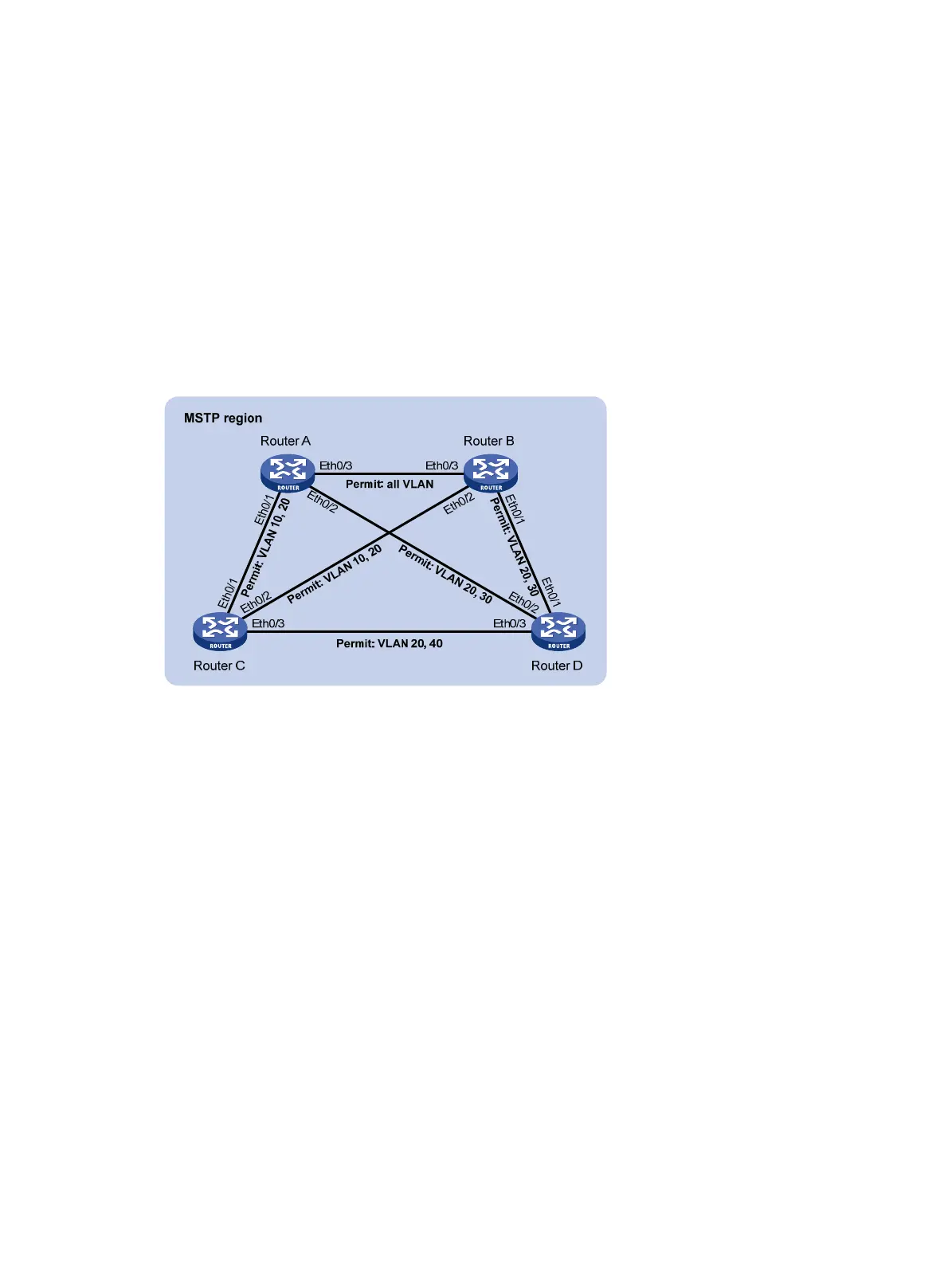
As shown in Figure 322, all routers on the network are in the same MST region. Router A and Router
B work on the distribution layer. Router C and Router D work on the access layer.
Configure MSTP so that packets of different VLANs are forwarded along different instances: packets
of VLAN 10 along MSTI 1, those of VLAN 30 along MSTI 3, those of VLAN 40 along MSTI 4, and
those of VLAN 20 along MSTI 0.
VLAN 10 and VLAN 30 are terminated on the distribution layer routers, and VLAN 40 is terminated
on the access layer routers, so the root bridges of MSTI 1 and MSTI 3 are Router A and Router B,
respectively, and the root bridge of MSTI 4 is Router C.
Figure 322 Network diagram
"Permit:" next to a link in the figure is followed by the VLANs the packets of which are permitted to
pass this link.
Configuration procedure
1. Configure VLANs and VLAN member ports (details not shown):
Create VLAN 10, VLAN 20, and VLAN 30 on Router A and Router B, respectively.
Create VLAN 10, VLAN 20, and VLAN 40 on Router C.
Create VLAN 20, VLAN 30, and VLAN 40 on Router D.
Configure the ports on these routers as hybrid ports and assign them to related VLANs.
Configure the security zones to which the combinations of these ports and their permitted
VLANs belong.
2. Configure Router A:
# Create an MST region named example, map VLAN 10, VLAN 30, and VLAN 40 to MSTI 1,
MSTI 3, and MSTI 4, respectively, and configure the revision level of the MST region as 0:
a. From the navigation tree, select Advanced > MSTP > Region.
b. On the page that appears, click Modify.
The page for modifying an MST region appears, as shown in Figure 323.
b. Config
ure the
region name as example.
c. Set the revision level to 0.
d. Select the Manual radio button.