30
Figure 387 Configuring interface Ethernet 0/1
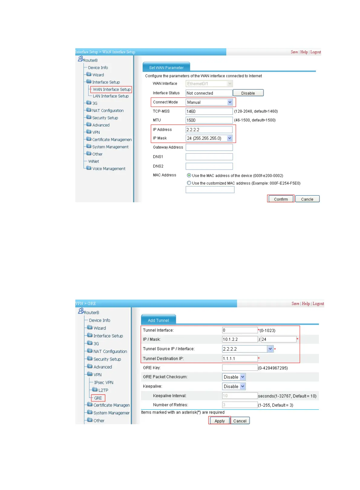
3. Create a GRE tunnel:
a. Select VPN > GRE from the navigation tree.
b. Click Add and then perform the configurations shown in Figure 388.
c. Enter 0 in the Tunnel Interf
ace field.
d. Enter IP address/mask 10.1.2.2/24.
e. Enter the source end IP address 2.2.2.2, the IP address of Ethernet 0/1.
f. Enter the destination end IP address 1.1.1.1, the IP address Ethernet 0/1 on Router A.
g. Click Apply.
Figure 388 Setting up a GRE tunnel
4. Configure a static route from Router B through interface Tunnel 0 to Group 1:
a. Select Advanced > Route Setup from the navigation tree.