4: Source-measure considerations Model 2450 Interactive SourceMeter® Instrument
4-6 2450-901-01 Rev. B/September 2013
Voltage limit boundary examples
The actual boundaries where the instrument operates depends on the device under test (DUT) that is
connected to the output of the instrument.
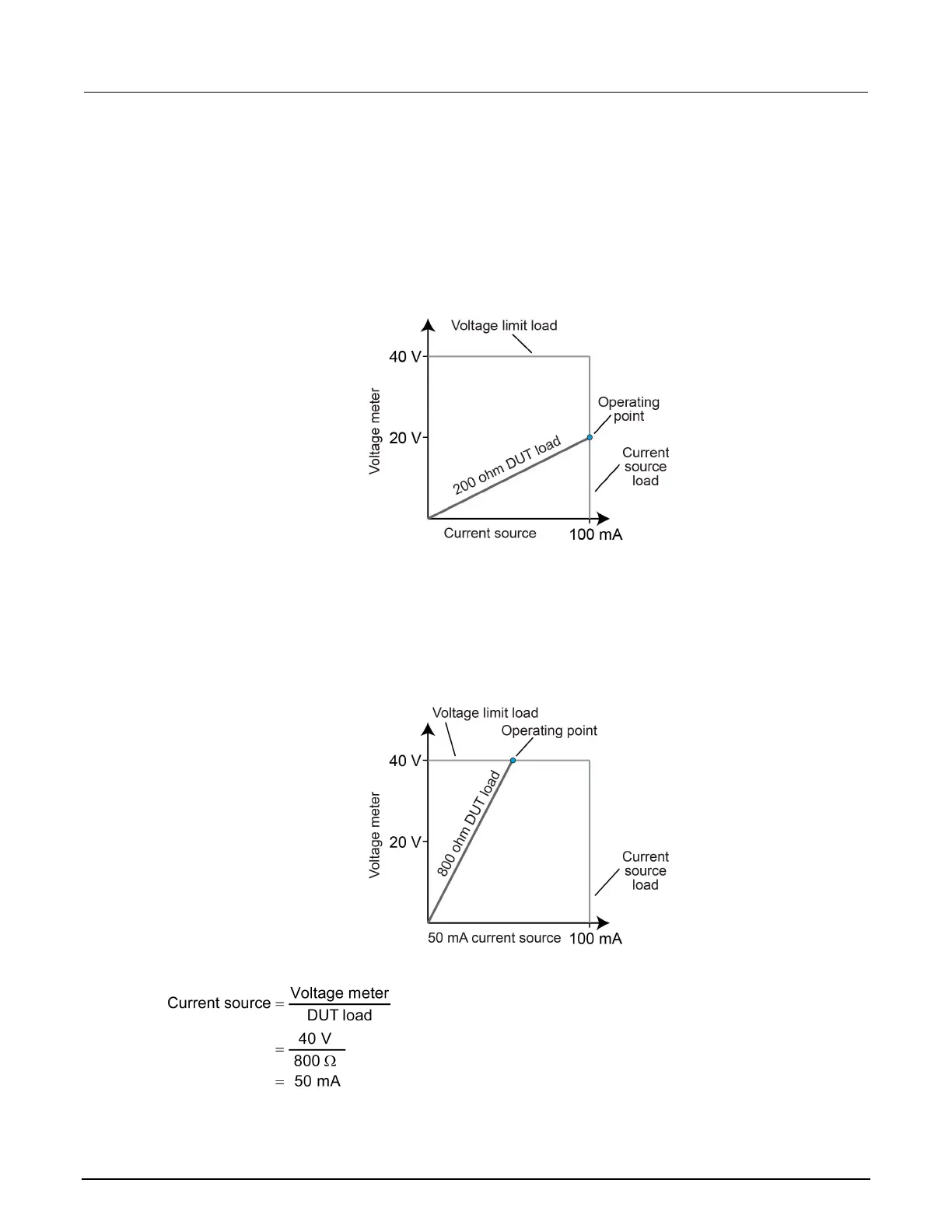
The following graphs show operation with the instrument set to source 100 mA with a limit of 40 V. In
this graph, the resistive load is 200 Ω. The instrument is sourcing 100 mA to the 200 Ω load and
subsequently measures 20 V. The load for 200 Ω intersects the 100 mA current source at 20 V.
Figure 111: Model 2450 limit boundary example — normal
Current source * DUT load
Ω
In the following graph, the resistive load is increased to 800 Ω. The DUT load for 800 Ω intersects the
voltage limit, which causes the instrument to limit the current that it is sourcing. For the 800 Ω DUT,
the instrument will only output 50 mA at the 40 V limit.
Figure 112: Model 2450 limit boundary example when limited