2: General operation Model 2450 Interactive SourceMeter® Instrument
2-72 2450-901-01 Rev. B/September 2013
Keithley Instruments connector CS-1616-3, supplied with the Model 2450, can be used to make the
interlock connection to the rear panel. You must supply connection wire.
To ensure proper interlock operation, the external interlock switch and connection wires must be less
than 10 ohms when the switch is closed.
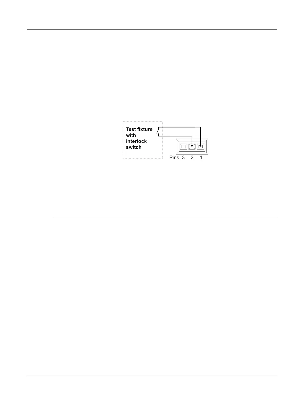
The pin locations and connections are shown in the following figure. The pins are:
• Pin 3: Earth and chassis ground
• Pin 2: Interlock
• Pin 1: +6 V DC out (current limited)
Figure 46: Model 2450 interlock pins
Front or rear panel test connections
You can use either the front-panel or rear-panel terminals to make connections to the device under
test (DUT). You cannot make some connections to the front-panel terminals and some to the
rear-panel terminals for the same test setup.
The instrument must be set to use the front or rear terminals.
Determining whether to use front or rear terminals
The terminals on the front panel are banana jack connectors, while the rear-panel terminals are
triaxial connectors. Depending on your test setup, the test environment, and the precision of your
measurements, you may see different results between measurements taken from the front and rear
terminals.
For the most precise measurements, use the rear-panel triaxial terminals. If you are making
measurements or sourcing current in the 10 nA and 100 nA ranges, you must use the rear-panel
triaxial terminals. You must also use the rear panel connections when making bipolar junction
transistor (BJT) measurements.
You might also want to use the rear-panel terminals if the test environment is electrically noisy. The
shielding on the triaxial cables will prevent environmental noise from affecting measurements.