Interactive SourceMeter® Instrument Reference Manual Section 2:
2450-901-01 Rev. B/September 2013 2-7
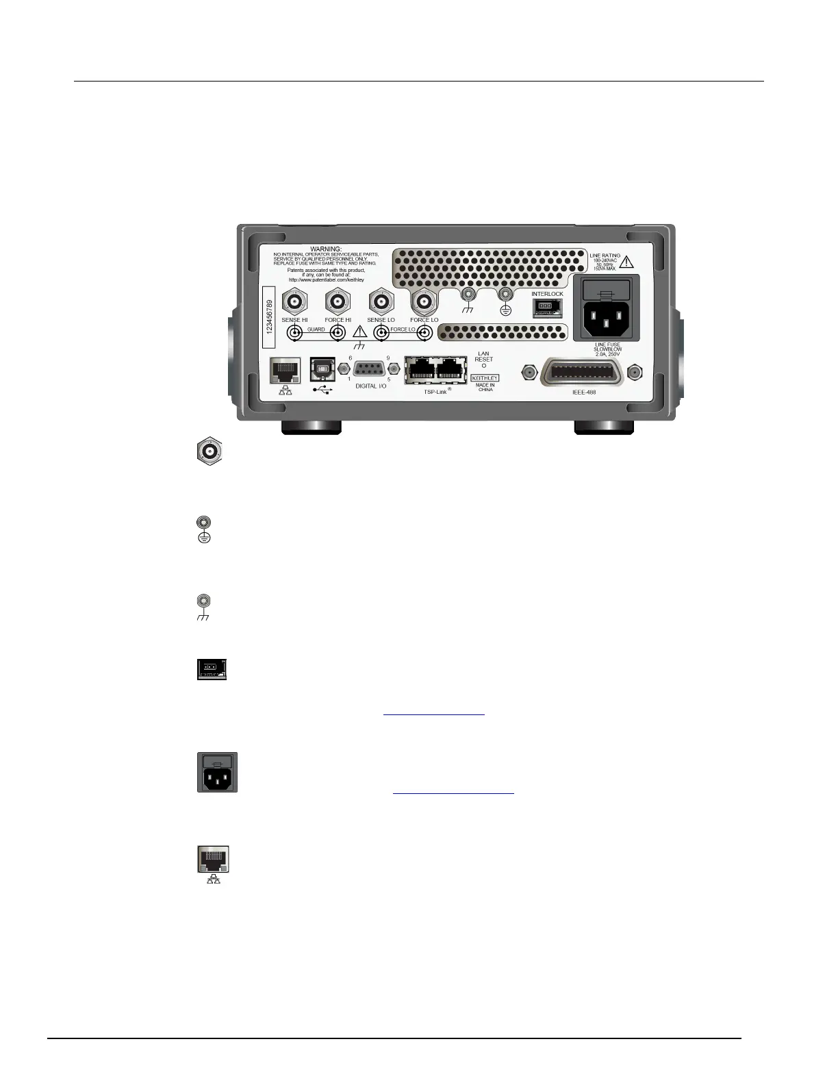
Rear panel overview
The rear panel of the Model 2450 is shown below; descriptions follow the figure.
Figure 3: Model 2450 rear panel
SENSE and FORCE
connectors
These triaxial terminals provide connections for SENSE HI and
SENSE LO, FORCE HI and FORCE LO, GUARD, and chassis
Protective earth
(safety ground)
Ground screw for connection to protective earth (safety ground).
Connect to protective earth using recommended wire size (#16
Chassis ground
Ground screw for connections to chassis ground. This provides a
connection terminal to the equipment frame.
Interlock connector
Interlock connection for use with an interlock switch, such as a
test fixture. When properly connected, the safety interlock of the
Model 2450 places the outputs of the instrument in a safe state.
For details, see Using the interlock (on page 2-70).
Line fuse and
power receptacle
The line fuse, located just above the power receptacle, protects
the power line input of the instrument. For safety precautions and
other details, see
Line fuse replacement (on page A-1) and Power
the instrument on and off.
LAN port
Supports full connectivity on a 10 Mbps or 100
Model 2450 is a LXI version 1.4 Core 2011 compliant instrument
that supports TCP/IP and complies with IEEE Std 802.3 (ethernet