Interactive SourceMeter® Instrument Reference Manual Appendix D:
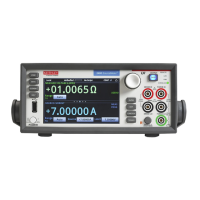
Model 2450 in a Model 2400 application
2450-901-01 Rev. B/September 2013 D-3
Commands that were added to the SCPI 2400 command set
To replace some features that are needed to use the Model 2450 in a Series 2400 application, the
following commands were added.
• :SYSTem:GPIB:ADDRess: Assigns a GPIB address through a remote interface. See
:SYSTem:GPIB:ADDRess (on page 6-104
) for detail.
• :SYSTem:TLINk: Sets the digital I/O port to digital I/O or trigger link. See below for detail.
:SYSTem:TLINk information
The usage for this command is:
:SYSTem:TLINk <n>
Where <n> is:
• 0: The DIGITAL I/O port on the rear panel of the instrument is set for digital I/O connections.
• 1: The DIGITAL I/O port on the rear panel of the instrument is set for trigger link.
When the port is set for digital I/O, the following signals are available on the digital I/O connector:
• Pin 1: Out 1
• Pin 2: Out 2
• Pin 3: Out 3
• Pin 4: Out 4 (end of test (EOT) or BUSY)
• Pin 6: Input (start-of-test (SOT))
The commands that support digital I/O and Trigger Link can be used with these settings. For
example, SOURce2:TTL can be used to set the I/O port bit pattern for the digital I/O state.
:ARM[:SEQuence[1]][LAYer[1]]:SOURce TLINk can be selected when the state is TLINk.
To use Trigger Link connections, you must use the Model 2450-TLINK DB-9 to Trigger Link
Connector Adapter.
If you have an application where you need to switch between the digital I/O and trigger link
connections, you can use the :SYSTem:TLINk command and recall setups (*SAV and *RCL) to
switch between the two states. After you save the setups, an example sequence is:
SYST:TLIN 0
*RCL 1
SYST:TLIN 1
*RCL 2
SYST:TLIN 0
*RCL 1
Model 2400 commands that are not supported in Model 2450
The Model 2450 introduced new features and hardware changes that made some earlier commands
obsolete. These commands are documented in this section.
 Loading...

