234 Keysight N9915-90020 User’s Guide
SA (Spectrum Analyzer) Mode (Option 233–Mixed Analyzers)FUTURE
How to Set Up EMF Settings (Requires EMF (Option 358), GPS (Option 307), and SA
Mode (Option 233–Mixed Analyzers))
See also, “How to Use the Manual EMF Channel Power” on
page 237
.
— Optional: Press
Antenna Axis the antenna axis should be set to Auto
for default operation. When AUTO is selected the application (e.g.,
Channel Power or OTA) controls the axes and switches as needed.
With the AUTO setting, all antenna elements (X, Y, and Z) are OFF.
This softkey is only active when Antenna Select is set to Tri Axial.
— Press
Back > Back to exit the USB Antenna softkey menu.
4. Enabling the imported USB antenna factors and Cable factors:
a. Verify that the Channel Power measurement is set: Measure 1
>
Channel Measurements > Channel Power
b. To enable the Triaxial antenna for EMF: Press Meas Setup 4 > EMF
Off > EMF Triaxial [OFF] > Sum All
With Sum All, the field strength from all three axes is summed and
displayed. The RF measurements are switched between the three
different antennas (three dipoles), and the resulting summation of
the total power collected, and averaged.
Alternatively, you can select either of three axes to individually
measure the field strength in the one direction.
c. Else, to manually set one of the triaxial antenna’s three axes to
individually measure the field strength in one direction.
i. Press EMF Off
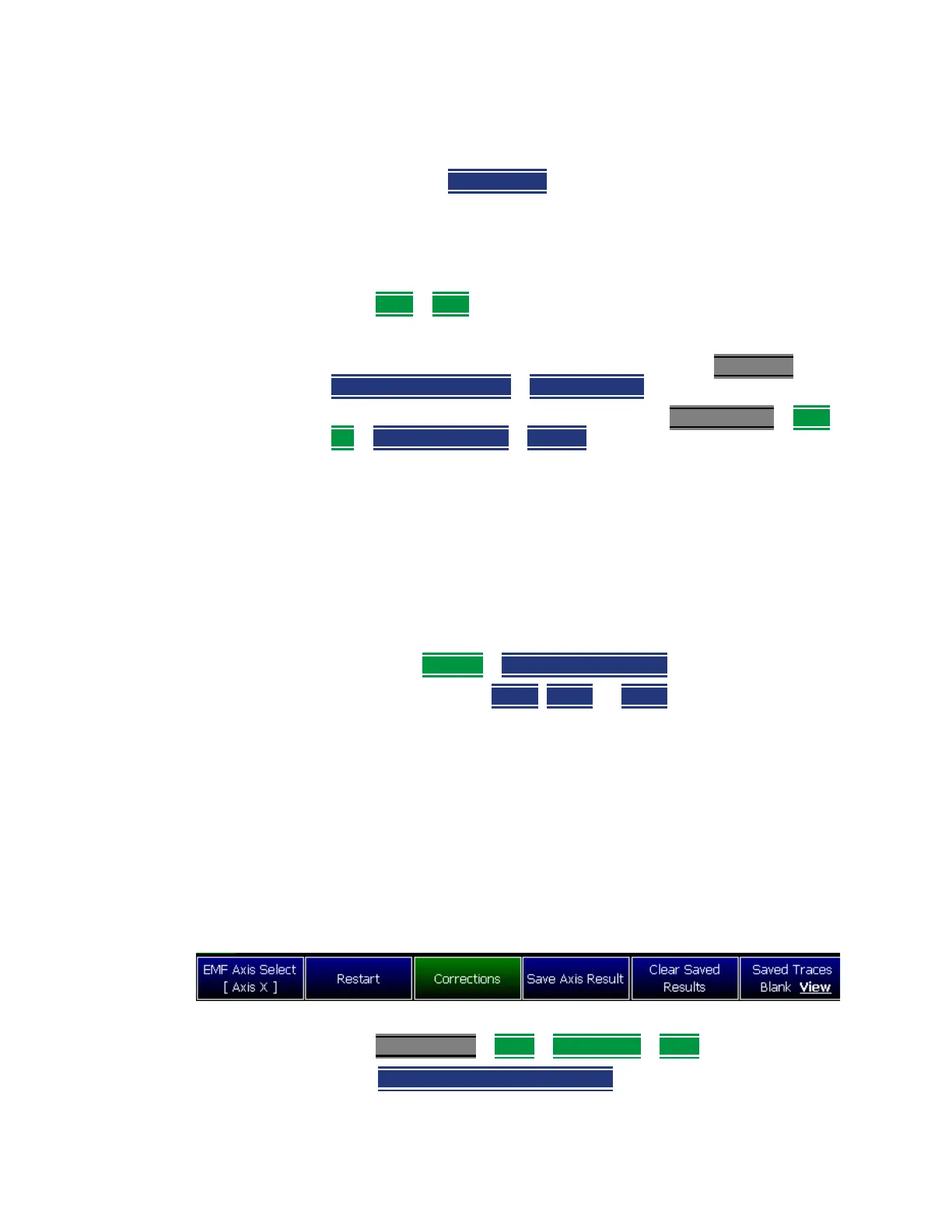
> EMF Axis Select [OFF] then
ii. Select a single
Axis X, Axis Y, or Axis Z antenna dipole for
uncorrected use. [X, Y, or Z] is displayed to indicate which
one of the X/Y/Z dipole axes is enabled. If for example the
X axis has been selected in the System > Utilities > EMF
Antennas menu, then Antenna Axis [X] is displayed to
indicate the X axis measurement (i.e., this uncorrected
manual mode is typically used when no EMF Option 358 is
installed). Refer to
Figure 9-24. See also step f.
For corrected manual single axis EMF measurements, refer to
“How to Use the Manual EMF Channel Power” on page 237.
Figure 9-24 EMF Axis Select [N] Softkey – With the X–Axis Dipole Selected
d. Modifying the Amplitude Correction Selection:
Press Scale/Amptd
> More > Corrections > More then
—
Amp Corr Select [Tri Axial XYZ] - then choose one of the
following: