15. SERVO AMPLIFIER CONNECTION
15.6 Device Range that Can Be Set
15 - 25
SERVO AMPLIFIER CONNECTION
15
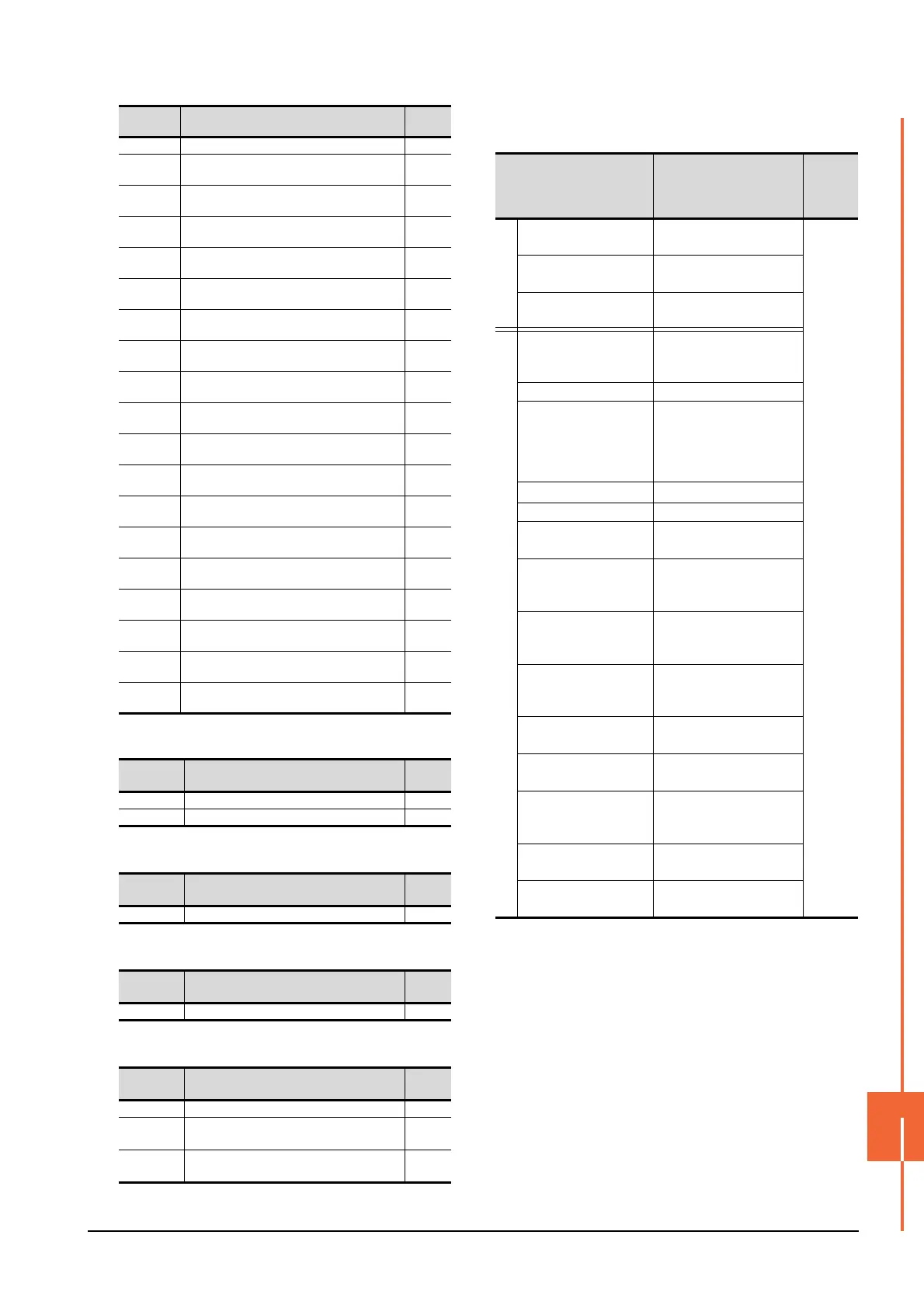
(g) External I/O signal
(h) Input signal for test operation (for test operation)
(i) Forced output of signal pin (for test operation)
(j) Set data (for test operation)
(5) MELSERVO-J2S-*CP
*1 Use PRM0 to PRM90 when writing parameters to the servo
amplifier RAM.
PRM1000 to PRM1090 are used when writing parameters to
E
2
PROM of the servo amplifier.
*2 When writing to a point table, use the area of 1001 to 1031
(E
2
PROM area) of POS, SPD, ACT, DCT, DWL, or AUX.
If writing to the area of 1 to 31 (RAM area) of POS, SPD,
ACT, DCT, DWL, or AUX, the value is not reflected.
*3 The GOT cannot read or write data from/to consecutive
devices.
*4 Only reading is possible for DI0 to DI1.
AL25 Servo status when alarm occurs bus voltage ―
AL200
Alarm number from alarm history
most recent alarm
―
AL201
Alarm number from alarm history
first alarm in past
―
AL202
Alarm number from alarm history
second alarm in past
―
AL203
Alarm number from alarm history
third alarm in past
―
AL204
Alarm number from alarm history
fourth alarm in past
―
AL205
Alarm number from alarm history
fifth alarm in past
―
AL210
Alarm occurrence time in alarm history
most recent alarm
―
AL211
Alarm occurrence time in alarm history
first alarm in past
―
AL212
Alarm occurrence time in alarm history
second alarm in past
―
AL213
Alarm occurrence time in alarm history
third alarm in past
―
AL214
Alarm occurrence time in alarm history
fourth alarm in past
―
AL215
Alarm occurrence time in alarm history
fifth alarm in past
―
AL230
Detailed alarm from alarm history
most recent alarm
―
AL231
Detailed alarm from alarm history
first alarm in past
―
AL232
Detailed alarm from alarm history
second alarm in past
―
AL233
Detailed alarm from alarm history
third alarm in past
―
AL234
Detailed alarm from alarm history
fourth alarm in past
―
AL235
Detailed alarm from alarm history
fifth alarm in past
―
Device
name
Item Symbol
DI0 External input pin statuses ―
DO0 External output pin statuses ―
Device
name
Item Symbol
TMI0 Input signal status for test operation ―
Device
name
Item Symbol
TMO0 Forced output status of signal pin ―
Device
name
Item Symbol
TMD0 Writes the speed (test mode) ―
TMD1
Writes the acceleration/deceleration time
constant (test mode)
―
TMD2
Writes the moving distance in pulses (test
mode)
―
Device
name
Item Symbol
Device name
*3
Setting range
Device
No.
represent
ation
Bit device
Servo amplifier request
(SP)
SP0 to SP6
Decimal
Operation mode selection
(OM)
OM0 to OM4
Instruction demand
(for test operation) (TMB)
TMB0 to TMB1
Word device
Basic parameter
/expansion parameter
(PRM)
*1
PRM0 to PRM90
PRM1000 to PRM1090
Status display (ST) ST0 to ST16
Alarm (AL)
AL0 to AL1
AL11 to AL27
AL200 to AL205
AL210 to AL215
AL230 to AL235
External input (DI)
*4
DI0 to DI2
External output (DO) DO0 to DO1
Point table
(position) (POS)
*2
POS1 to POS31
POS1001 to POS1031
Point table
Point table (speed)
(SPD)
*2
SPD1 to SPD31
SPD1001 to SPD1031
Point table
(acceleration time
constant) (ACT)
*2
ACT1 to ACT31
ACT1001 to ACT1031
Point table
(deceleration time
constant) (DCT)
*2
DCT1 to DCT31
DCT1001 to DCT1031
Point table
(dwell) (DWL)
*2
DWL1 to DWL31
DWL1001 to DWL1031
Point table
(auxiliary function) (AUX)
*2
AUX1 to AUX31
AUX1001 to AUX1031
Input signal for test
operation
(for test operation) (TMI)
TMI0
Forced output of signal pin
(for test operation) (TMO)
TMO0
Set data
(for test operation) (TMD)
TMD0 to TMD2

 Loading...


