15 - 26
15. SERVO AMPLIFIER CONNECTION
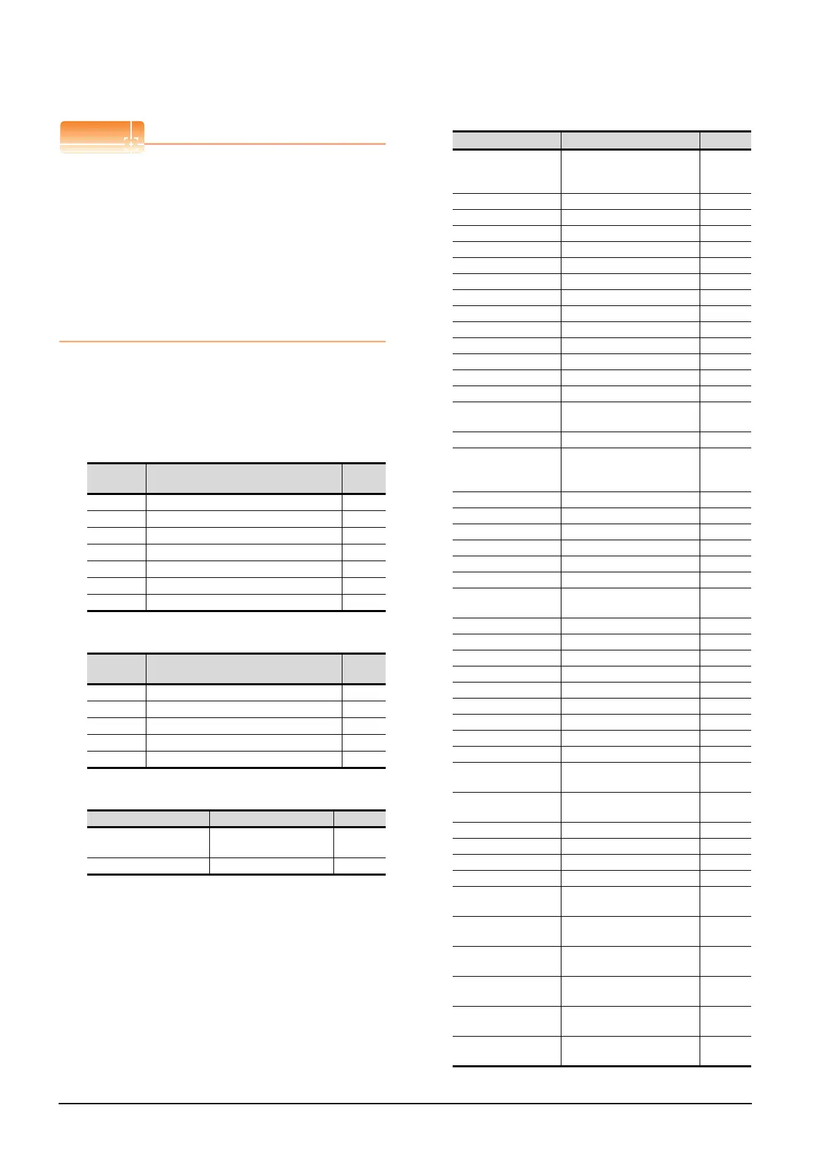
15.6 Device Range that Can Be Set
Precautions for SP, OM, TMB, TMI, TMO, and TMD
devices
(1) For bit devices
Only writing is possible.
[Alternate] of a bit switch cannot be used.
Use [Set], [Reset], and [Momentary] of a bit
switch.
(2) For word devices
Only writing is possible.
Numerical input cannot be used.
When writing, use [Word Set] of a data set switch.
The following shows correspondences between virtual
devices for servo amplifier and data of the servo
amplifier used with the GOT.
(a) Servo amplifier request
(b) Operation mode selection
(c) Instruction demand (for test operation)
(d) Basic parameter/expansion parameter
Device
name
Item Symbol
SP0 Status display data clear ―
SP1 Current alarm clear ―
SP2 Alarm history clear ―
SP3 External input signal prohibited ―
SP4 External output signal prohibited ―
SP5 External input signal resumed ―
SP6 External output signal resumed ―
Device
name
Item Symbol
OM0 Normal mode (not test operation mode) ―
OM1 JOG operation ―
OM2 Positioning operation ―
OM3 Motorless operation ―
OM4 Output signal (DO) forced output ―
Device name Item Symbol
TMB0
Clears the acceleration/
deceleration time constant
―
TMB1 Temporary stop command ―
Device name Item
Symbol
*1
PRM0, PRM1000
Command system/
regenerative brake option
selection
*STY
PRM1, PRM1001 Feeding function selection *FTY
PRM2, PRM1002 Function selection 1 *OP1
PRM3, PRM1003 Auto tuning ATU
PRM4, PRM1004 Electronic gear numerator *CMX
PRM5, PRM1005 Electronic gear denominator *CDV
PRM6, PRM1006 In-position range INP
PRM7, PRM1007 Position loop gain 1 PG1
PRM8, PRM1008 Home position return type *ZTY
PRM9, PRM1009 Home position return speed ZRF
PRM10, PRM1010 Creep speed CRF
PRM11, PRM1011 Home position shift distance ZST
PRM12, PRM1012 Rough match output range CRP
PRM13, PRM1013 Jog speed JOG
PRM14, PRM1014
S-pattern acceleration/
deceleration time constant
*STC
PRM15, PRM1015 Station number setting *SNO
PRM16, PRM1016
Serial communication function
selection,
alarm history clear
*BPS
PRM17, PRM1017 Analog monitor output MOD
PRM18, PRM1018 Status display selection *DMD
PRM19, PRM1019 Parameter block *BLK
PRM20, PRM1020 Function selection 2 *OP2
PRM21, PRM1021 For manufacturer setting ―
PRM22, PRM1022 Function selection 4 *OP4
PRM23, PRM1023
Serial communication time-out
selection
SIC
PRM24, PRM1024 Feed forward gain FFC
PRM25, PRM1025 Override offset VCO
PRM26, PRM1026 Torque limit offset TLO
PRM27, PRM1027 Encoder output pulses *ENR
PRM28, PRM1028 Internal torque limit 1 TL1
PRM29, PRM1029 Internal torque limit 2 TL2
PRM30, PRM1030 Backlash compensation *BKC
PRM31,PRM1031 Analog monitor 1 offset MO1
PRM32, PRM1032 Analog monitor 2 offset MO2
PRM33, PRM1033
Electromagnetic brake
sequence output
MBR
PRM34, PRM1034
Ration of load inertia moment
to servo motor inertia moment
GD2
PRM35, PRM1035 Position control gain 2 PG2
PRM36, PRM1036 Speed control gain 1 VG1
PRM37, PRM1037 Position control gain 2 VG2
PRM38, PRM1038 Speed integral compensation VIC
PRM39, PRM1039
Speed differential
compensation
VDC
PRM40 to PRM41,
PRM1040 to PRM1041
For manufacturer setting ―
PRM42, PRM1042
Home position return position
data
*ZPS
PRM43, PRM1043
Moving distance after
proximity dog
DCT
PRM44, PRM1044
Moving distance
after proximity dog
ZTM
PRM45, PRM1045
Stopper type home position
return torque limit value
ZTT

 Loading...


