May 2001
System Hardware Manual 5 - 121
A6-324000-642-01 – Release 4.0
May 2001
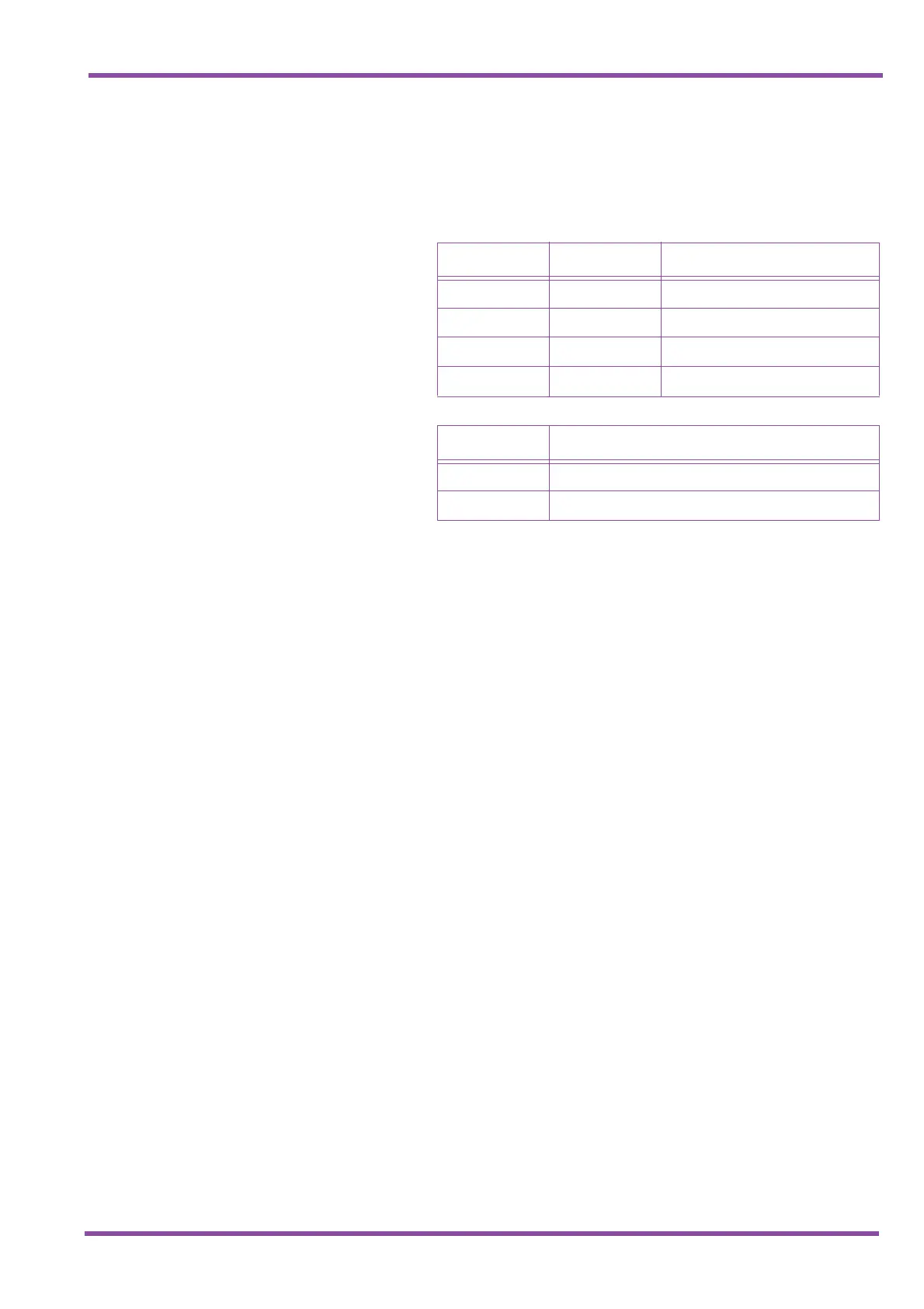
3.6.3 Switch Settings
Refer to Table 5-3 MIFA-U13 ETU Switch Settings for
MIFA-U13 ETU default switch settings.
3.6.4 LED Indications
LIVE LED indications are listed below.
✆ Blinking Red Normal Operation
✆ Steady Red Operation Stopped (power still on)
✆ Off No Power
LED1 indications are listed below
✆ Steady Red Problem while loading FROM from
EEPROM (when using this mode)
✆ Steady Red PC Programming or LCR
Programming is connected
✆ Flashing Red Loading FROM from EEPROM
3.6.5 Connectors
The following connectors are located on the MIFA-U13
ETU.
✆ CN1 Connects to the Backboard
✆ CN2 Connects to the Backboard
✆ CN3 Connects the ETU backup battery. It
connects the battery during
installation, and disconnects the
battery when storing the ETU.
✆ IC6 Socket for the optional KMA
(XXX)UA Unit (applicable to Xen
Master Only)
Table 5-3 MIFA-U13 ETU Switch Settings
SW2-1 SW2-2 Description
Off
Off
Normal Operation
On Off Factory Test
Off On
Not Used
On On Flash ROM load from EPROM
SW1 Description
On System boot by Flash ROM
Off System boot by EPROM

 Loading...


