May 2001
System Hardware Manual 5 - 137
A6-324000-642-01 – Release 4.0
May 2001
4.8.3 Switch Settings
Refer to Table 5-6 TLI(2)-U13 ETU Default Switch
Settings.
4.8.4 LED Indications
Live LED indications are listed below.
✆ Blinking Red Normal Operation
✆ Steady Red Operation Stopped (power still on)
✆ Off No Power
CH 1 ~ CH 2 indications are listed below.
✆ Steady Red Lines 1~2 busy
✆ Off Lines 1~2 idle
4.8.5 Connectors
The following connector is located on the TLI(2)-U13 ETU.
✆ CN1 Connects to the backboard
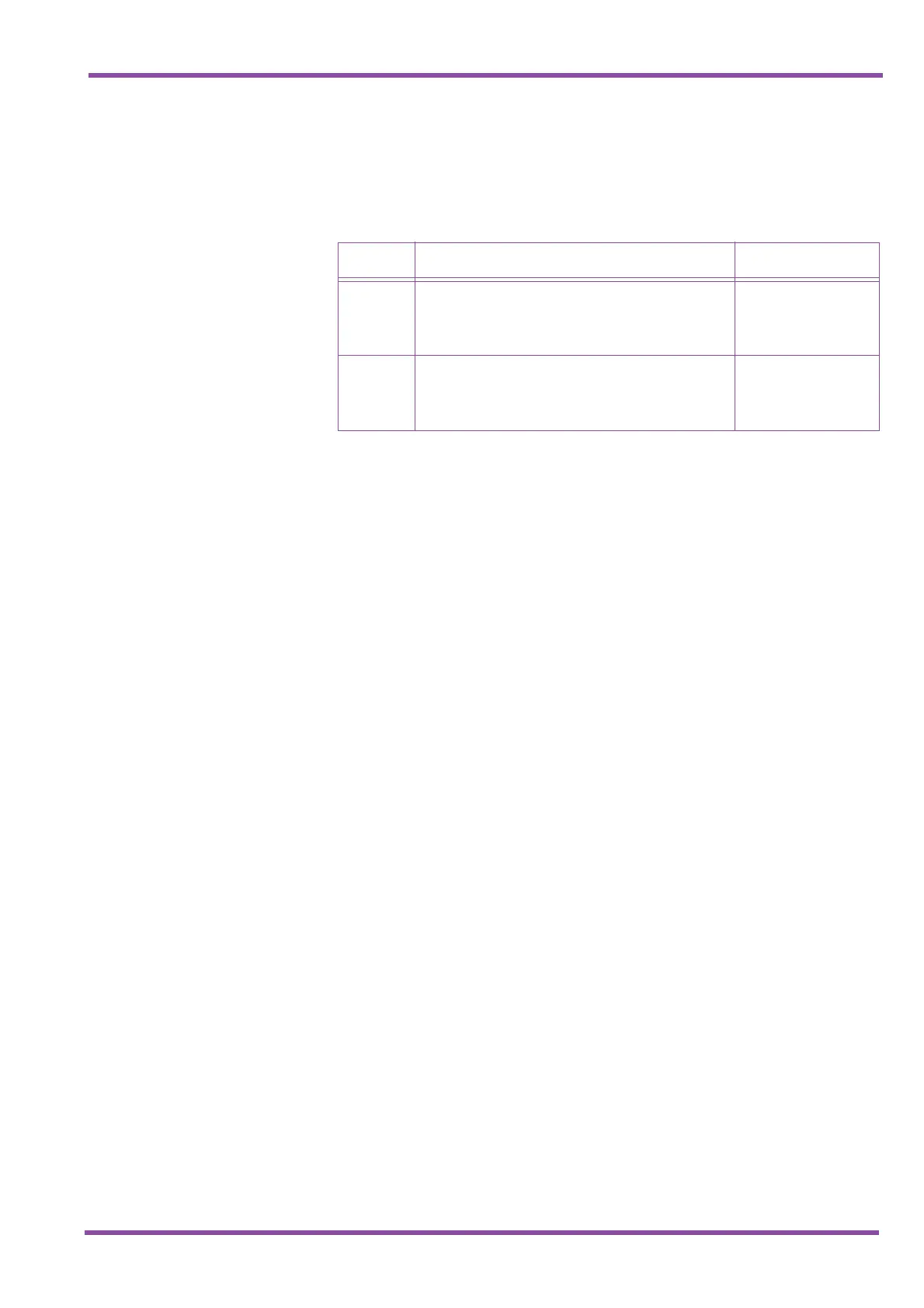
Table 5-6 TLI(2)-U13 ETU Default Switch Settings
Switch Setting Description
SW101
When lines provided by this unit are used for back-to-
back connections, set to Type V.
When connection is to a Central Office, set to Type I.
Default: Type V
Switch between Type I
or Type V for Line 1
SW201
When lines provided by this unit are used for back-to-
back connections, set to Type V.
When connection is to a Central Office, set to Type I.
Default: Type V
Switch between Type I
or Type V for Line 2

 Loading...


