NEC Australia Pty Ltd Xen Master & Xen Axis
5 - 160 Installing Electronic Telephone Units
A6-324000-642-01 – Release 4.0
May 2001
5.3.7 Connectors
The following connectors are located on the VDH2(8)-U13
ETU.
✆ CN1 Connects to the backboard.
✆ CN2 – CH1~7 Connects to Multiline Terminals.
✆ CN2 – CH8 Connects to Multiline Terminal or
cascade connection to another HUB.
✆ CN3 Connects 10Base-2 cascade cables
from another HUB or mainframe LAN.
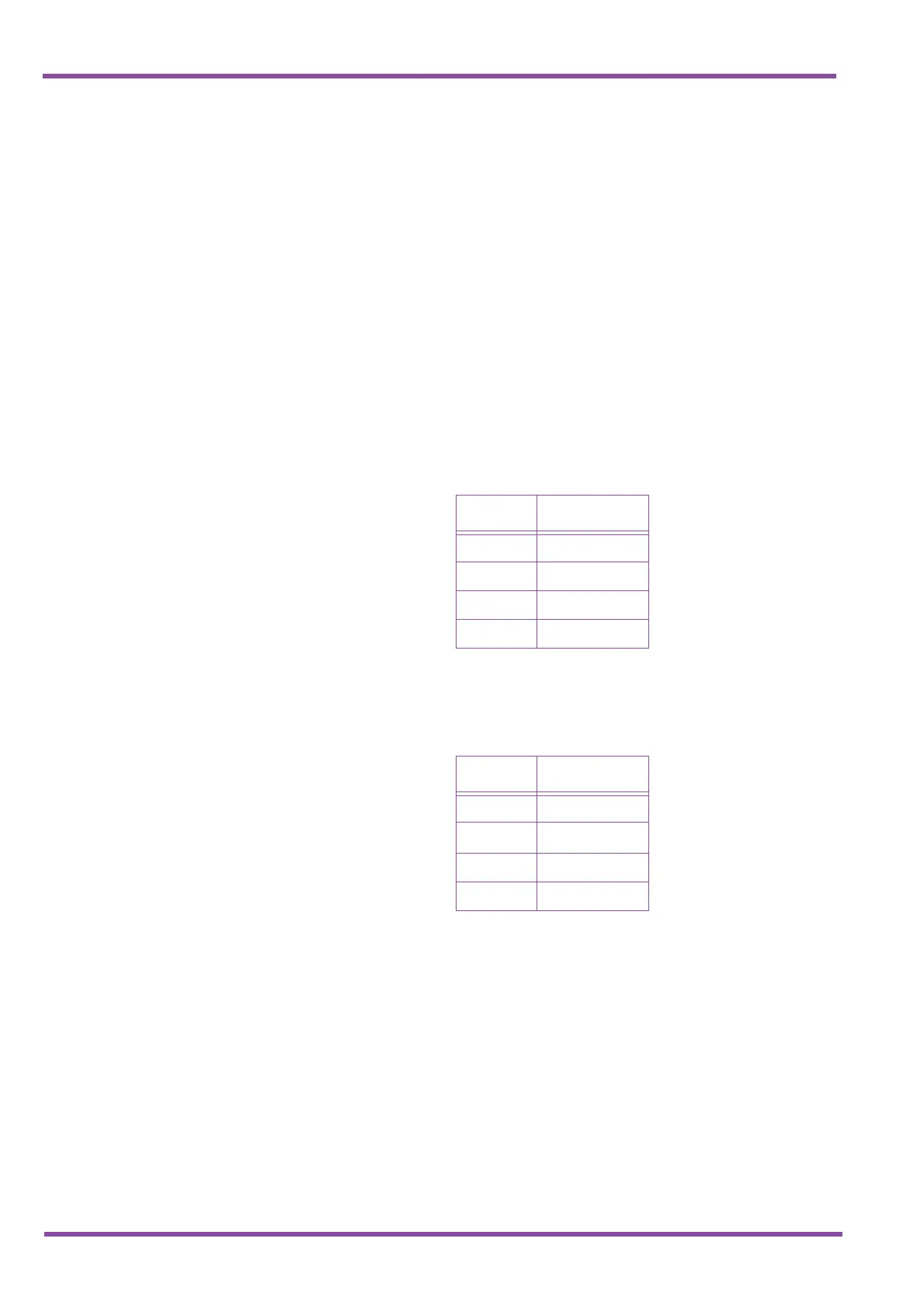
When SW2 is set to X, the following table indicates the pin
assignments for the RJ-45 pins for CN2 – CH8.
In the tables below, TD indicates Transmit Data and RD
indicates Receive Data.
When SW2 is set to =, the following table indicates the pin
assignments for the RJ-45 pins for CN2-CH8.
Note: Cables that connect a terminal to a HUB are straight, and
cables that connect HUB-to-HUB are crossed. Core line
uses straight cables only.
Table 5-11 Normal
Pin Signalling
6TD-
3TD+
2 RD-
1RD+
Table 5-12 Cascade
Pin Signalling
6 RD-
3
RD+
2TD-
1TD+

 Loading...


