May 2001
System Hardware Manual 7 - 237
A6-324000-642-01 – Release 4.0
May 2001
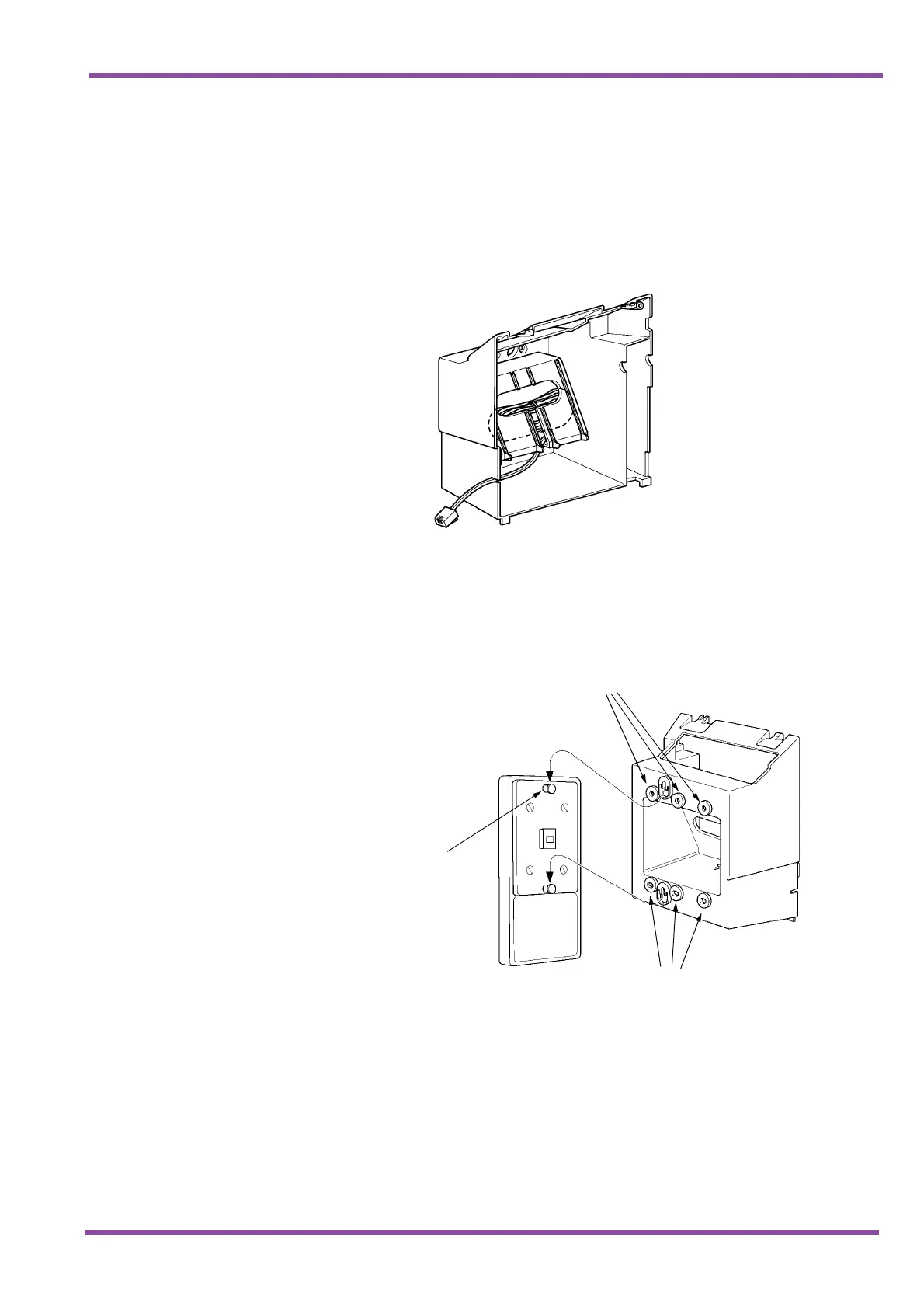
4. Bundle the cord from the modular jack leaving about
eight inches. Use a tie wrap to secure the
bundled cord.
5. Place the bundled line cord in the space between the
WMU-UA Unit and the wall. Lead the line cord out
through the slits as shown in Figure 7-71 Leading the
Line Cord out of the WMU-UA Unit.
6. Attach the WMU-UA Unit to the posts on the wall
plate (locally provided). Place locally provided screws
in the nodes on the WMU-UA Unit and secure the
WMU-UA Unit to the wall.
7. Connect the line cord to the Multiline Terminal.
Figure 7-71 Leading the Line Cord out of the WMU-UA Unit
Figure 7-72 Attaching the Wall Mount Unit to the Wall
Posts
Nodes
Nodes

 Loading...


