NEC Australia Pty Ltd Xen Master & Xen Axis
4 - 48 Installing KSUs
A6-324000-642-01 – Release 4.0
May 2001
2.4 Cabling to the Main Distribution Frame (MDF)
The Xen KSU is connected to each of the Multiline Terminals, Single
Line Telephones, optional equipment, CO/PBX, DID, ISDN, on a 4-
wire E&M Tie lines (Types I and V) by separate twisted-pair cable
through the MDF. The 4-wire E&M Tie lines and ISDN lines require
multiple twisted-pair cabling. Refer to Table 4-1 MDF Cable
Connections - Xen Master and Refer to Table 4-3 MDF Cable
Connections - Xen Axis which provide the necessary cabling
information.
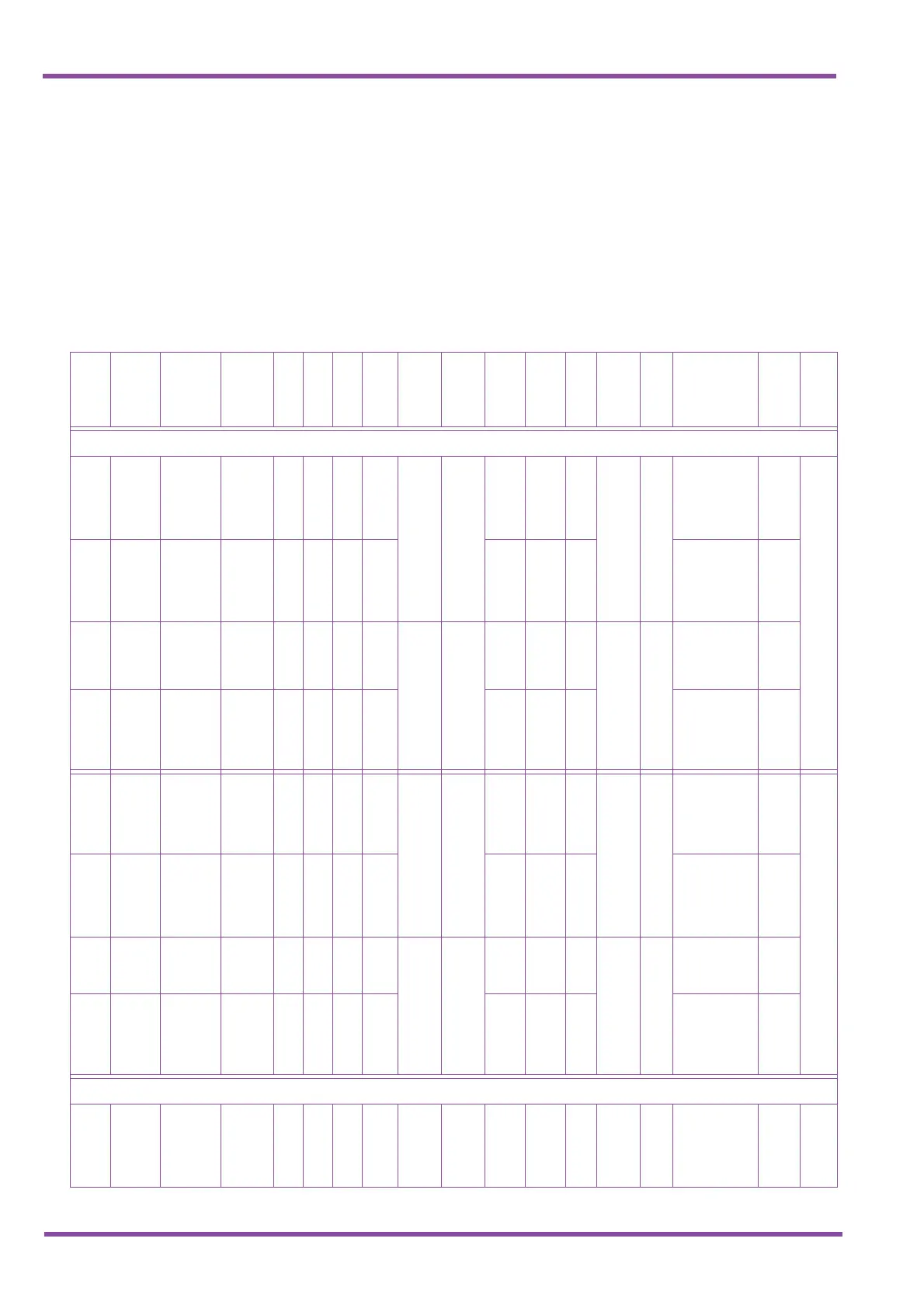
Table 4-1 MDF Cable Connections - Xen Master
MDF Pin
No.
Circuit
No.
Running
Cable
Station
Cable
ESI(8)
SLI(8)
SLI(4)
OPX(2)
BIU(2)
BSU(2)
COI/
COID(8)
COI/
COID(4)
DID(4)
BRI(4)
PRI(1)
ECR
DPH
TLI(2)
First ETU
26
1
WH–BL BK T T T T -Rx-1 -Rx-1 T T T
+Rx-
1
+R
x
EP
Zone 3
DP1
GN
D
1 BL–WH YL R R R R
+Rx-
1
+Rx-
1RRR-Rx-1-Rx
27
2
WH–OR BK T T T T -Tx-1 -Tx-1 T T T
+Tx-
1
+T
x
EP
Zone 2
DP2
E-1
2 OR–WH YL RRR R
+Tx-
1
+Tx-
1 R R R -Tx-1 -Tx M-1
28
3
WH–GN BK T T T T T T
+Rx-
2
EP
Zone 1
DP3
T-1
3 GN–WH YL R R R R R R -Rx-2 R-1
29
4
WH–BR BK T T T T T T
+Tx-
2
Night Chime DP4
T1-
1
4 BR–WH YL RRR R R R-Tx-2
R1-
1
30
5
WH–SL BK T T -Rx-2 -Rx-2 T
+Rx-
3
External
Tone
Ringer 4
DLR
1
GN
D
5 SL–WH YL R R
+Rx-
2
+Rx-
2 R -Rx-3
31
6
RD—BL BK T T -Tx-2 -Tx-2 T
+Tx-
3
External
Tone
Ringer 3
DLR
2
E-2
6 BL–RD YL R R
+Tx-
2
+Tx-
2 R -Tx-3 M-2
32
7
RD-OR BK T T T -Rx-4 External
Tone
Ringer 2
DLR
3
T-2
7 OR–RD YL R R R -Rx-4 R-2
33
8
RD–GN BK T T T +Tx-r
External
Tone
Ringer 1
DLR
4
T1-
2
8 GN–RD YL R R R -Tx-4
R1-
2
Second ETU
34
1
RD–BR BK T T T T -Rx-1 -Rx-1 T T T
+Rx-
1
+R
x
EP
Zone 3
DP1
GN
D
9 BR–RD YL R R R R
+Rx-
1
+Rx-
1RRR-Rx-1-Rx

 Loading...


