May 2001
System Hardware Manual 5 - 163
A6-324000-642-01 – Release 4.0
May 2001
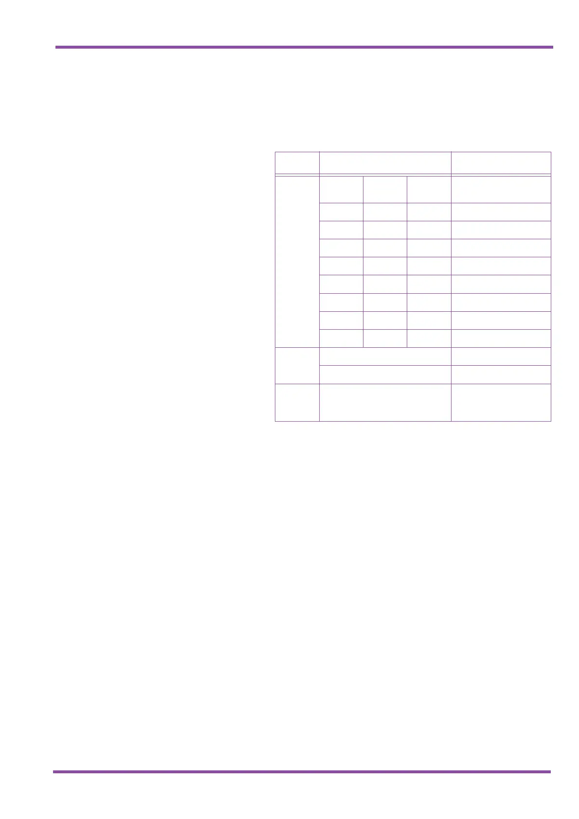
5.4.3 Switch Settings
The following table indicates the default switch settings for
the VRS(4)-U13 ETU.
5.4.4 LED Indications
Live LED indications are listed below.
✆ Blinking Red Normal Operation
✆ Steady Red Operation Stopped (power still on)
✆ Off No Power
BSY 1~4 indications are listed below.
✆ Steady Red Channels 1~4 are busy with replay/
record or detecting DTMF signals
✆ Off Channels 1~4 are idle
5.4.5 Connectors
The following connector is located on the VRS(4)-U13
ETU.
✆ CN1 Connects to the backboard
5.4.6 Pins
There are two jumpers labelled SP1 and SP2 located on
the top right of the VRS ETU. These are for maintenance
purposes. Do not change the factory default settings on
these pins. Pins 2 and 3 are to remain short-circuited.
Table 5-14 VRS(4)-U13 ETU Default Switch Settings
Switch Setting Description
SW1–1
SW1–2
SW1–3
SW1–1 SW1–2 SW1–3
Record decibel
adjustment
Off Off Off 0 decibels (default)
On Off Off 1 decibel
Off On Off 2 decibels
On On Off 3 decibels
Off Off On 4 decibels
On Off On 5 decibels
Off On On 6 decibels
On On On 7 decibels
SW1–4
On Record Gain
Off Record Pad (default)
SW2 N/A
Test Switch
and
Reset Switch

 Loading...


