Remote Commands
R&S
®
FSW
1120User Manual 1173.9411.02 ─ 43
For more information see Chapter 8.2.1.3, "IF and Video Signal Output", on page 364.
Suffix:
<up>
.
Parameters:
<Frequency> *RST: 50.0 MHz
Default unit: HZ
Manual operation: See "Data Output" on page 437
OUTPut<up>:UPORt:STATe <State>
This command toggles the control lines of the user ports for the AUX PORT connector.
This 9-pole SUB-D male connector is located on the rear panel of the R&S FSW.
Suffix:
<up>
.
irrelevant
Parameters:
<State> ON | OFF | 0 | 1
OFF | 0
User port is switched to INPut
ON | 1
User port is switched to OUTPut
Example:
OUTP:UPOR:STAT ON
OUTPut<up>:UPORt[:VALue] <Value>
This command sets the control lines of the user ports.
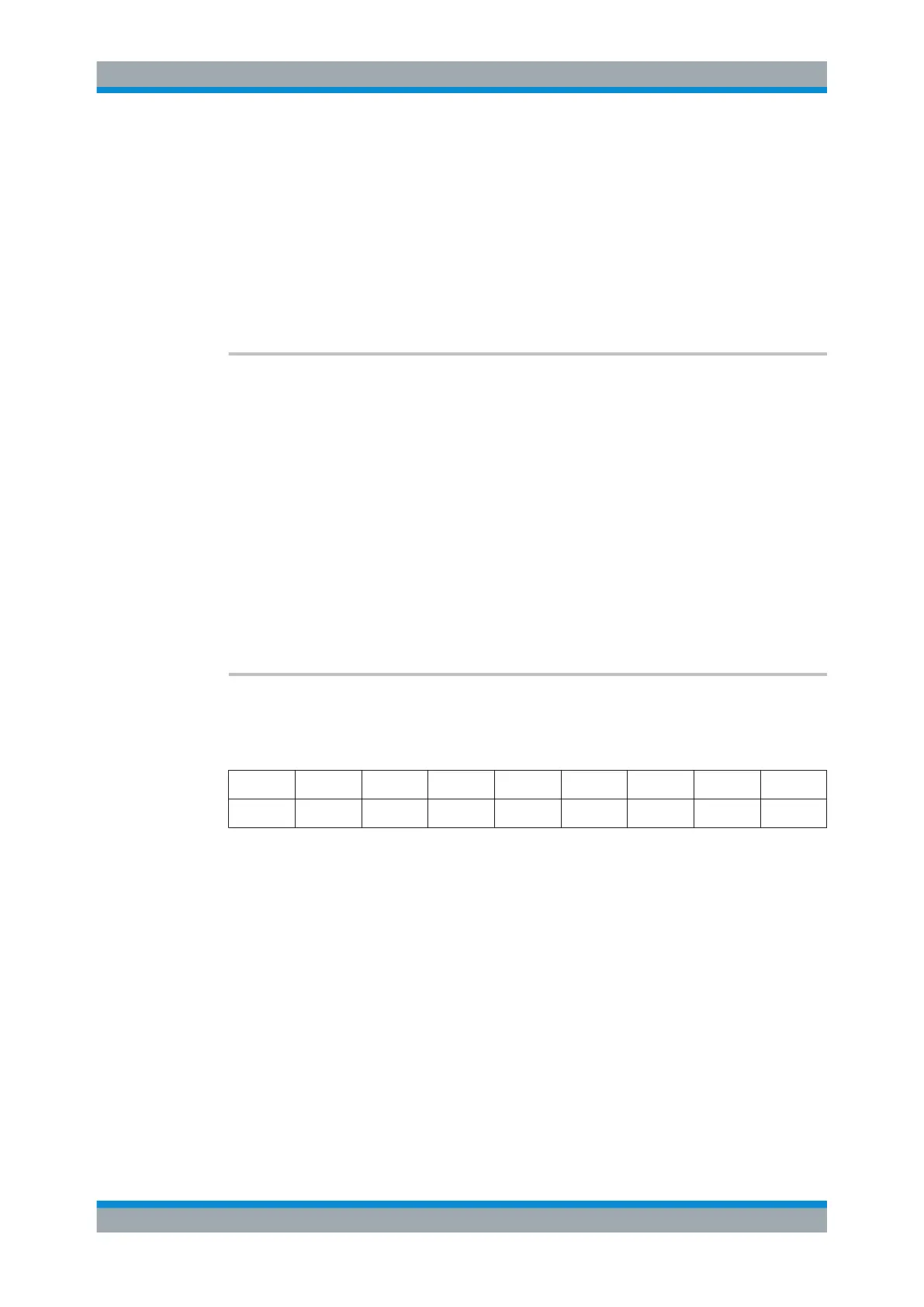
The assignment of the pin numbers to the bits is as follows:
Bit 7 6 5 4 3 2 1 0
Pin N/A N/A 5 3 4 7 6 2
Bits 7 and 6 are not assigned to pins and must always be 0.
The user port is written to with the given binary pattern.
If the user port is programmed to input instead of output (see INPut<ip>:UPORt:
STATe on page 1073), the output value is temporarily stored.
Suffix:
<up>
.
irrelevant
Parameters:
<Value> bit values in hexadecimal format
TTL type voltage levels (max. 5V)
Range: #B00000000 to #B00111111
Example:
OUTP:UPOR #B00100100
Sets pins 5 and 7 to 5 V.
Setting Basic Measurement Parameters

 Loading...


