Common Analysis and Display Functions
R&S
®
FSW
544User Manual 1173.9411.02 ─ 43
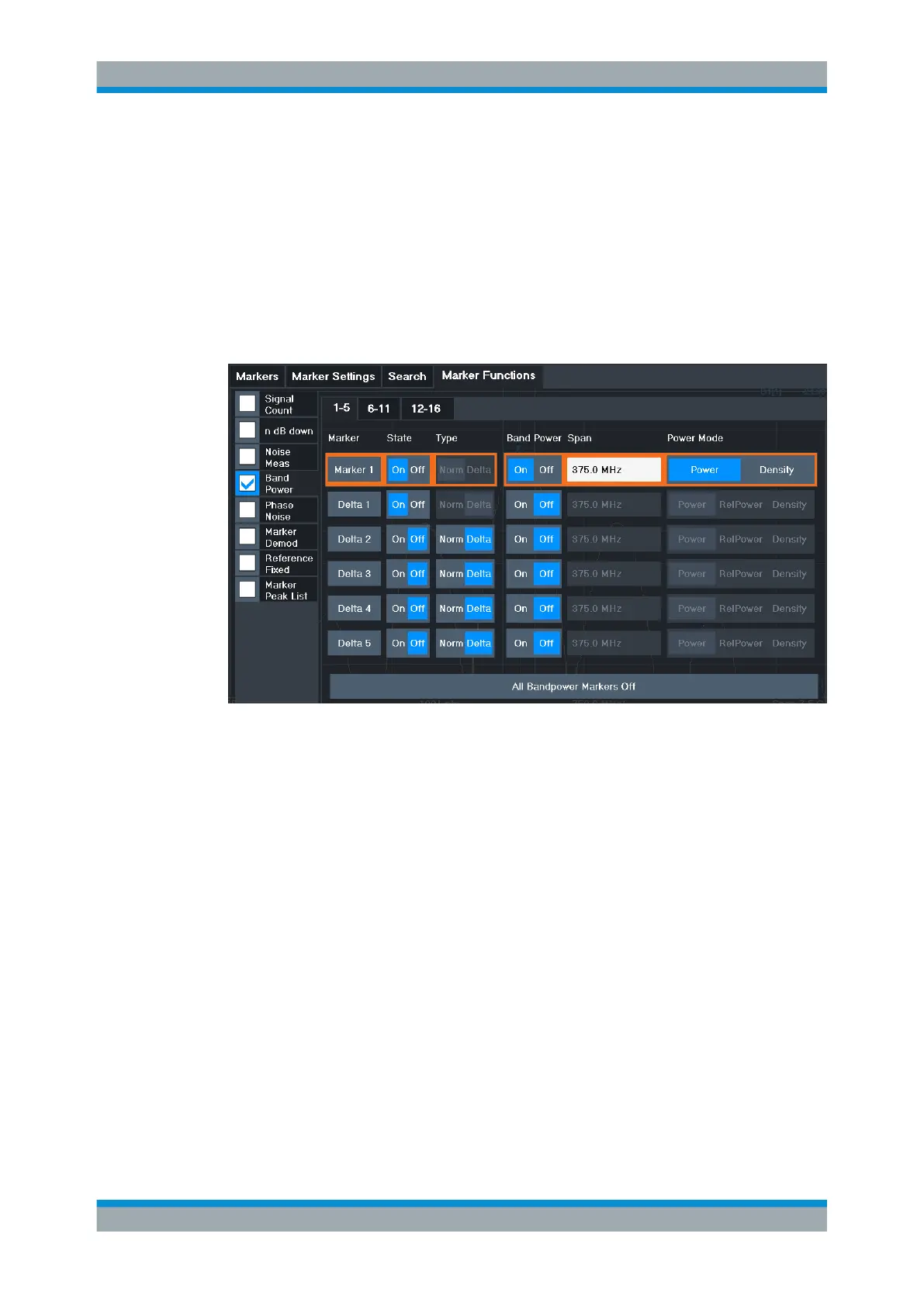
All markers can be defined as band power markers, each with a different span. When a
band power marker is activated, if no marker is active yet, marker 1 is activated. Other-
wise, the currently active marker is used as a band power marker (all other marker
functions for this marker are deactivated).
If the detector mode for the marker trace is set to "Auto", the RMS detector is used.
The individual marker settings correspond to those defined in the "Marker" dialog box
(see Chapter 9.3.2.1, "Individual Marker Setup", on page 519). Any settings to the
marker state or type changed in the "Marker Function" dialog box are also changed in
the "Marker" dialog box and vice versa.
Remote commands:
"Example: Measuring the Power in a Channel Using Band Power Markers"
on page 1205
CALCulate<n>:MARKer<m>:FUNCtion:BPOWer[:STATe] on page 1190
CALCulate<n>:MARKer<m>:FUNCtion:BPOWer:RESult? on page 1189
Band Power Measurement State................................................................................ 544
Span............................................................................................................................545
Power Mode................................................................................................................545
Switching All Band Power Measurements Off.............................................................545
Band Power Measurement State
Activates or deactivates band power measurement for the marker in the diagram.
Band power markers are only available for standard frequency measurements (not
zero span) in the Spectrum application.
If activated, the markers display the power or density measured in the band around the
current marker position.
For details see Chapter 9.3.4.6, "Measuring the Power in a Channel (Band Power
Marker)", on page 542.
Marker Usage

 Loading...


