Screws: polished round/spring (M4×10)
Hexagon flange screws (M4×8)
Tapping bind screws (3×8)
Installation Procedure
For instructions on unpacking and installing the Caster Table Type M40, please refer to the operating
instructions "Caster Table Type M40 Installation Guide".
When installing with the paper feed unit
Installation by service representative may be required when installing Caster Table Type M40 with
Paper Feed Unit PB1160, depending on the machine configuration.
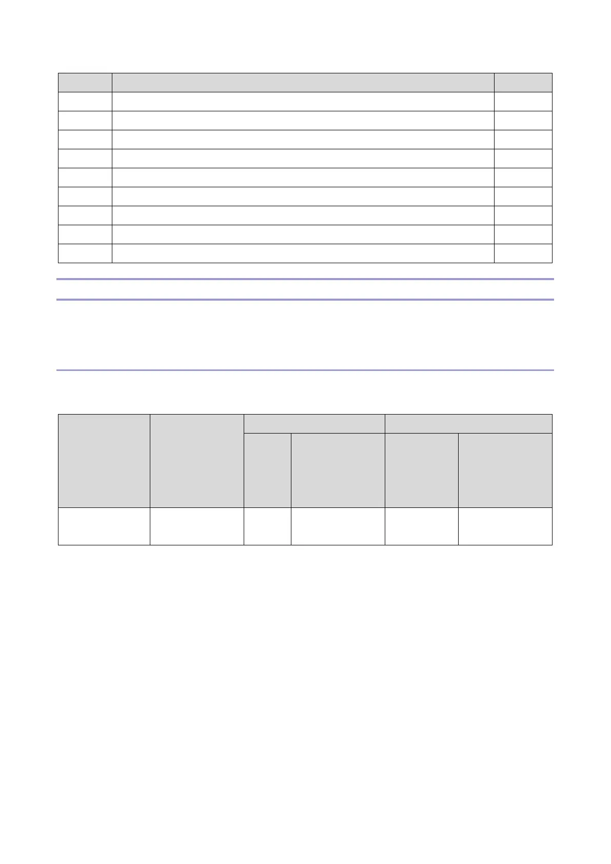
Printer only,
or with 1
PFU
PB1160
Who can install
the caster table
*1 The attaching stands and connecting parts need to be installed to prevent the machine from falling
over. If it falls or topples over, an injury might occur. For instructions on installing Paper Feed Unit
PB1160 and Caster Table Type M40, please refer to Installation Procedure.
 Loading...