Section 13 PROPULSION
Subsection 02 (DRIVE SYSTEM)
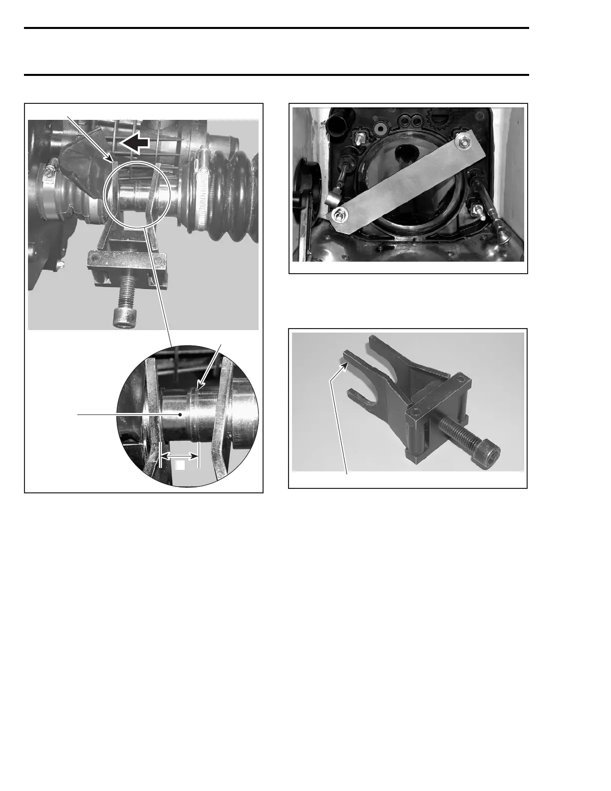
1
F18I0PA
2
3
A
TYPICAL
1. Largest opening here
2. Tell tale groove
3. Lubricate O-rings contact area
A. 18 mm (.71 in)
Turn screw clockwise so that the tool pushes the
PTO seal forward and the drive shaft to the rear to
expose the O-rings contact area. Continue to pull
drive shaft out until there is a distance of 18 mm
(.71 in) between the tell tale groove and the tool
edge. Lubricate O-rings contact area with BOM-
BARDIER LUBE (P/N 293 600 016).
NOTE: This is necessary to ease drive shaft re-
moval later in this procedure.
Remove drive shaft/floating ring tool and PTO seal
support.
Reinstall drive shaft holder tool.
F18B03A
Reinstall drive shaft/floating ring tool as shown.
Push floating ring rearwards to expose circlip and
remove it.
1
F18I0OA
TYPICAL
1. Largest opening on PTO seal side
660 smr2004-Complete Line Up

 Loading...


