39 Programmable Hardware Manual (PHM)
© Tibbo Technology Inc.
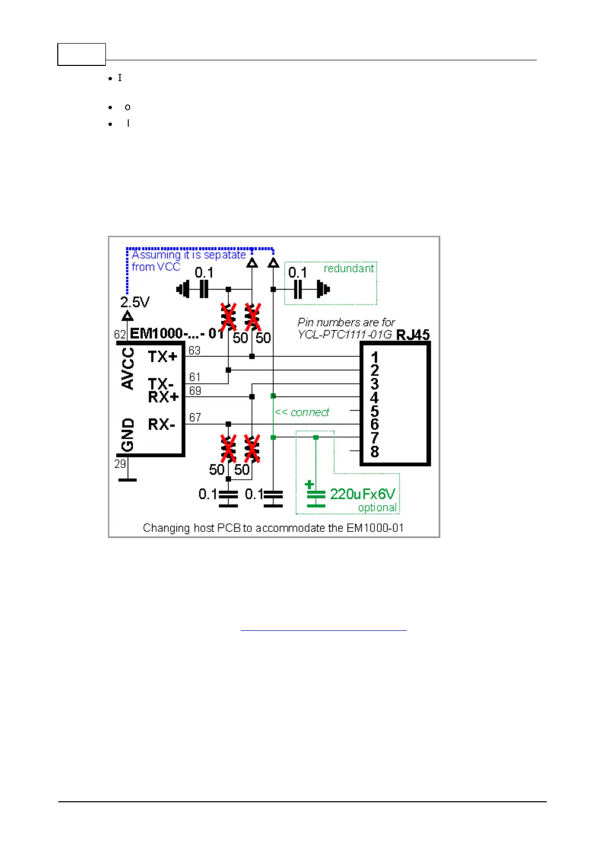
·
If possible, find a way to install a 220uF capacitor. The circuit will still work even
if you don't have this capacitor but you may have FCC/CE certification issues.
·
Notice that one of the 0.1 capacitors becomes redundant but that's OK.
·
All of the above is based on the assumption that your host PCB was designed
correctly and the AVCC output of the EM1000 is not joined together with the main
VCC line. If you erroneously had AVCC and VCC combined together then you will
need to separate them as well: pin AVCC outputs 2.5V on the EM1000-...- 01
and this is different from the main power on the VCC pin, which is 3.3V. Applying
3.3V to pin AVCC of the EM1000-...- 01 appears to be causing no immediate
permanent damage to the device, but the circuit will not work and the effects of
prolonged over-voltage on the AVCC line are not known.
It is important to make the PCB wire connections between the Ethernet port pins of
the EM1000 and external magnetics circuitry as short as possible. Making the wires
too long may cause the noise level generated by your PCB to surpass the maximum
radiated emission limits stipulated by FCC/CE regulations. Additionally, longer
Ethernet lines on the PCB will make your board more susceptible to the damage from
the ESD (electrostatic discharge).
The EM1000 also has two Ethernet status LED control lines- see here for details.

 Loading...