5. CONFIGURATION
was intercepted, the function block informs that a command was intercepted through bCommandAvailable parameter. The
intercepted command information are then filled in the sCommand and eStatus output parameters, according to the received
command type. This operation depends only of the received command type, don’t matter the variable’s data type to which is
being intercepted the command. The interception is finished and then the function block can be released to intercept a new
command when bDone parameter is true. Yet must be pointed the command processing result in eCommandResult.
An application example of the commands interceptor, using ST language, that forwards a command received by the IEC
60870-5-104 Server to a Nexto Series digital output double point, can be found at section Digital Output Double Points.
5.5.5. MODBUS RTU Master
This protocol is available for the Nexto Series CPUs in its serial channels. By selecting this option at MasterTool IEC XE,
the CPU becomes MODBUS communication master, allowing the access to other devices with the same protocol, when it is
in the execution mode (Run Mode).
There are two configuration modes for this protocol. One makes use of Direct Representation (%Q), in which the variables
are defined by its address. The other, called Symbolic Mapping has the variables defined by its name.
Regardless of the configuration mode, the steps to insert a protocol instance and configure the serial interface are the same.
The procedure to insert a protocol instance is found in detail in the MasterTool IEC XE User Manual - MU299609 or in the
section Inserting a Protocol Instance. The remaining configuration steps are described below for each mode.
Add the MODBUS RTU Master Protocol instance to the serial channel COM 1 or COM 2 (or both, in case of two
communication networks). To execute this procedure, see Inserting a Protocol Instance section.
Configure the serial interface, choosing the transmission speed, the RTS/CTS signals behavior, the parity, the channel
stop bits, among others configurations by a double click on the COM 1 or COM 2 serial channel. See Serial Interfaces
Configuration section.
5.5.5.1. MODBUS Master Protocol Configuration by Symbolic Mapping
To configure this protocol using symbolic mapping, you must perform the following steps:
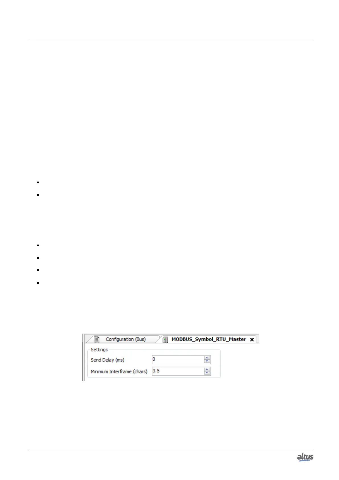
Configure the general parameters of the MODBUS Master protocol, like: transmission delay times and minimum inter-
frame as in Figure 56.
Add and configure devices via the General Parameters tab, defining the slave address, communication time-out and
number of communication retries as can be seen in Figure 57.
Add and configure the MODBUS mappings on Mappings tab as Figure 58, specifying the variable name, data type, and
the data initial address, the data size and range are filled automatically.
Add and configure the MODBUS requests as presented in Figure 59, specifying the function, the scan time of the request,
the starting address (read/write), the data size (read/write) and generate diagnostic variables and disabling the request
via the buttons at the bottom of the window.
5.5.5.1.1. MODBUS Master Protocol General Parameters – Symbolic Mapping Configuration
The general parameters, found on the MODBUS protocol initial screen (figure below), are defined as:
Figure 56: MODBUS RTU Master Configuration Screen
104

 Loading...